Article Content
Introduction
In recent years, sun-shading systems have been increasingly implemented on curtain walls of medium to high- rise buildings. The building envelope plays a primary role in the long-term energy efficiency and resilience of the building. Nevertheless, static facades offer only one design solution and cannot ensure high performance over seasonal times, especially in moderate climates that necessitate reduced heat gains in summer and increased solar penetration in winter [1]. On the other hand, adaptive sun-shading systems can be adjusted to the solar radiation, allowing optimal control [2, 3]. Such systems may provide a real-time process of reconfiguration on a daily and seasonal basis enlivening the environmental performance of the building and enhancing the end-users’ internal comfort [4].
Common shading systems implemented in the past years, include among others, mechanized venetian blinds, louvres, overhangs and perforated screens. Antoni Gaudi, Eileen Gray, Jean Prouvé and Buckminster Fuller already implemented concepts of flexibility and functionality into the building facade. Adaptive facade modules have been successfully implemented in contemporary buildings such as the Al Bahar Towers in the United Arab Emirates, Melbourne Council House 2 in Australia and Q1 ThyssenKrupp Headquarter Building in Germany. Existing adaptive system typologies are distinguished based on their key characteristics in [5], while current trends of adaptive facades are investigated with particular emphasis on their performance assessment in [6]. The design of adaptive shading systems, including their technical establishment and the methods applied for their performance evaluation are discussed in [7].
In the design of adaptive shading systems, basic critical parameters constitute the geometry of the members, the connections and the boundary conditions. These parameters define the kinematics of the systems, i.e., the transformational possibilities and kinetic characteristics, e.g., direction and magnitude of transformation [8]. In this framework, different typologies can be produced from every type of movement based on the degrees of freedom (DOF) related to geometrical restrictions, such as the number of coordinate axes [9]. 3-DOF can be identified for each type of motion based on the form of change in position, or orientation about one, two, or three axes. For example, rotation can produce three different typologies: swivel (restricted rotation), revolve (free rotation) and swing (off-center rotation flap) [8]. Moreover, combining two primary movements, i.e., translation and rotation, can generate other typologies, such as expanding, contracting, folding, directional twist, or rolling.
Most existing adaptive facades are composed of rigid body mechanisms that require multiple actuators in the kinematics of the systems. The actuators are operated by electricity, hydraulics, or pneumatics. Such systems are often disadvantageous, due to their high operational costs and energy consumption, as well as complex functionality. On the other hand, form-finding strategies can be implemented in the development of adaptive compliant systems, i.e., consisting of members with reversibly elastic deformability. In such systems, the material’s properties of the elastic members, particularly those of low elastic modulus, E, and high yield strength, σRd, enable increased reversible elastic deformability, providing single- or multi-curvature configurations [10,11,12]. As opposed to a rigid body mechanism, whereby inner stresses developed in the members should not exceed the section’s maximum load-bearing capacity, the acting load or pressure in the elastic members can be visually expressed by their own shape deformation [13, 14].
An adaptive lightweight building envelope system with integrated thin-film photovoltaic modules that also acts for sun-shading purposes is presented and investigated in its kinematics and load-deformation behavior in [15]. The structural unit consists of a cable net spanning an aluminum frame in support of a secondary system of struts and continuous cables responsible for the support of the photovoltaic modules as well as actuation of the system. The design concept of an adaptive building envelope membrane system is presented in [16]. The primary structure is composed of scissor-like elements and bending-active members interconnected in series through continuous tension-only members with closed loop. A further recent example of a textile-based hybrid system with adaptive properties is the “Soft-house” project. The responsive façade is formed by textile membranes with embedded photovoltaic (PV) cells and glass fiber-reinforced polymer (GFRP) members, resulting in a hybrid system of form- and bending-active members [17]. A further example is the kinetic media façade of the Thematic Pavilion for the Expo 2012 in Yeosu, South-Korea. The sun-shading system consists of 108 kinetic GFRP louvers, which span over the entire height of the facade of 3.0 to 13.0 m. These are supported on the top and bottom edge by fixed supports on one corner and linear actuators on the other corner. The actuators push the upper and lower edges together and lead to an elastic bending and a side rotation of the GFRP elements [18]. Further to the system kinematics, both latter examples highlighted some further desirable properties of GFRP, such as the high strength-to-weight ratio, corrosion resistance and aesthetic appeal.
Reflecting on the examples above, the current paper refers to a hybrid unitized curtain-wall system design with integrated adaptive sun-shading units directly supported on the panels’ split mullions. The façade units can be entirely prefabricated and assembled prior to an on-site installation. The adaptive system relies on the elastic deformability of GFRP plate elements that are kinematically controlled at scissor-like element supports through modification of their relative opening angles. Thus, the complexity of the system in its kinematics is reduced, while a minimum number of actuators has been implemented out of the element body, i.e., at the supports. The sun-shading units have been initially presented in their design composition and parametric associative design of their deformed shapes in [19]. The present paper presents results of the Finite-Element Analysis (FEA) of the corresponding bending-active plate of the units for symmetrical deformations induced by actuation of its supports. The analysis considers the self-weight of the plate and a uniform distributed load acting perpendicularly on the plate’s surface of 1 kN/m2. The study explores three different plate thicknesses (4, 5 and 6 mm) in selecting the most favorable thickness. The plate with selected thickness is then perforated by 15, 21, 28 and 36% of the total area. Two alternative perforation patterns are examined for each perforation ratio. The findings of this study can inform the design and optimization of GFRP sun-shading units for enhanced structural integrity in architectural applications. The next section presents the design concept of the sun-shading units and the analysis procedure of the system series, followed by the numerical results for the system with different plate thicknesses and perforation patterns with a selected plate thickness. The last section includes the main conclusions of the study.
Design concept
The proposed sun-shading units consist of a multi-series configuration, featuring a bending-active GFRP plate, which is strategically positioned over the height of each unitized curtain wall panel. These plates are supported at their four corners by scissor-like elements made of steel bars measuring 50 cm in length. The scissor-like elements are connected to an aluminum U-channel using brackets and custom-designed aluminum pressure plates, which are further fastened to the split mullion of the panels. A comprehensive depiction of the sun-shading units and their connection principle is shown in Fig. 1.
The GFRP plates possess a rectangular geometry, measuring 1.4 m in both, length and width. To induce elastic deformations in the connected bending-active plate, a rotating actuator is installed on the pin connection of each pair of scissor-like elements, i.e., brackets. The actuator enables modification of the opening angle of the elements, resulting in corresponding alteration of the curvature of the bending-active plate. By manipulating the actuation of the scissor-like elements, various curvatures of the bending-active plates can be achieved. Once the opening angle of the scissor like elements is obtained, their connection joint is locked. Figure 1 illustrates the resulting shape of the bending-active plate when all four actuating angles are at 45 degrees.

Façade unit design concept: a) Unit elevation (left) and vertical section (right), b) Horizontal section showing the joint and connection between adjacent units, c)-e) Vertical section of adjacent units
Structural model
The GFRP plate has been modelled using quadrilateral elements in a 14 × 14 mesh. The study explores three different plate thicknesses (4, 5 and 6 mm). The GFRP plate’s material properties refer to a Young’s modulus of 30 GPa and a yield strength of 500 MPa. The scissor-like elements are constructed from S355 structural steel with a solid square section measuring 25 × 25 mm. The steel properties, including a Young’s modulus of 210 GPa and a yield strength of 355 MPa, have been considered in the structural model. To accurately simulate the motion of the scissor-like elements, pretensioned steel cables with 10 mm diameter been employed as substitutes for the actuators. By adjusting the length of the cable elements, the desired opening angle of the scissor-like elements can be achieved. Figure 2 illustrates the initial and deformed shapes of the bending active plate for specific scissor-like elements relative opening angles, namely 0, 15, 30, and 45 degrees.
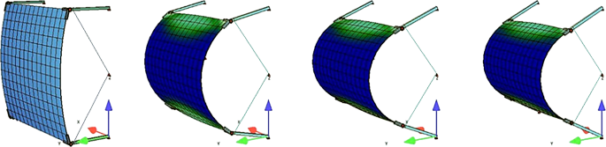
Initial and deformed shapes of bending-active plate for scissor-like elements’ relative opening angles of 0, 15, 30 and 45 degrees from left to right
Although the design concept employs rotating actuators installed on the pin connections of the scissor-like elements to modify their opening angles, the structural model adopts an equivalent strategy using pretensioned steel cables. This substitution was preferred to simplify the numerical model and ensure a stable and effective representation of the system within the analysis software. A force at the scissor-like elements’ free ends is applied by shortening the cables at specific lengths, inducing the same angular displacement of up to 45 degrees of the scissor-like elements’ members as the rotating actuators in the concept design. Notably, the resulting kinematics and deformation of the bending-active GFRP plate remain identical in both actuation strategies.
Analysis procedure
The numerical investigation of the sun-shading unit model was conducted through a progressive form-finding and load-deformation FEA with the software program SOFiSTiK® [20]. The plate’s bending was simulated by taking into consideration both the self-weight of the panel and internal material stresses, as well as the external wind load. The system simulations are based on the nonlinear third-order theory, considering geometrical nonlinearities and large displacements. In addition, a linear stress-strain behavior of the material of the elastic plate has been assumed in the analysis, to focus on the geometrical aspects of the active formation process of the element. The materials and cross-sections were defined through AQUA [21], a module of SOFiSTiK’s main database, while the geometrical definition of the system was produced through the McNeel Rhinoceros program [22]. The SOFiLOAD module [23] was used for the definition of the load, while ASE [20] was used as the general static analysis solver. SOFiLOAD and ASE were handled through the alternative text input tool provided by SOFiSTiK, TEDDY. The analysis follows an incremental induction of bending deformation, where inner stresses of the material developed in each step are stored in the model [24]. Figure 3 reflects the analysis stages and workflow.
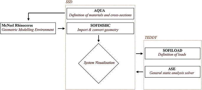
FEA analysis stages and workflow
The focus of the study is to investigate the response of the GFRP plate under its actuating loads, specifically due to the relative opening angle of the scissor-like elements. The analysis is conducted by applying the same actuating angle to all four corners of the plate, and the results are recorded for opening angles ranging from 0 to 45 degrees with a step increment of 5 degrees. The study examines the structural behavior of a bending-active plate under self-weight and an external wind load of 1 kN/m2 acting perpendicularly on the plate’s surface. The results provide a comprehensive understanding of the plate’s performance under both static and dynamic loading conditions.
The study did not consider the long-term behavior of the GFRP material. In real scale applications, adaptive bending-active structures rely on an advantageous long-term behavior, allowing for cyclic exposure of large elastic deformations. In view of the requirement for fatigue control, GFRP offers a ratio of σRd / E > 10 (with σRd (MPa) and E (GPa)) as discussed in [25]. Nevertheless, since composite materials like GFRP can exhibit a relative complex and less predictable fatigue behavior caused by cyclic long-term loading, a stress limit (maximum stress due to cyclic loading to permissible stress) of approximately 60% should be considered [26, 27]. The effect of stress level, concentration and frequency on the fatigue life of GFRP were studied through experimental, analytical and FEA in [28].
Numerical analysis
GFRP plate thickness
The first step for the numerical analysis of the GFRP plate was conducted using three different thickness values of 4, 5 and 6 mm. This preliminary analysis aims to select the most favorable thickness of the GFRP plate, which will be used for the next analysis step that considers specific perforation percentages and alternative patterns. The analysis conducted provided among others, results on the maximum plate’s deformation and stress for the three different thickness values. This analysis considered the relative opening angle of the scissor-like elements, the plate’s self-weight and an external wind load of 1 kN/m2 acting perpendicularly on the plate’s surface. To summarize the findings, Table 1 provides an overview of the maximum recorded values and Fig. 4 presents corresponding FEA results.
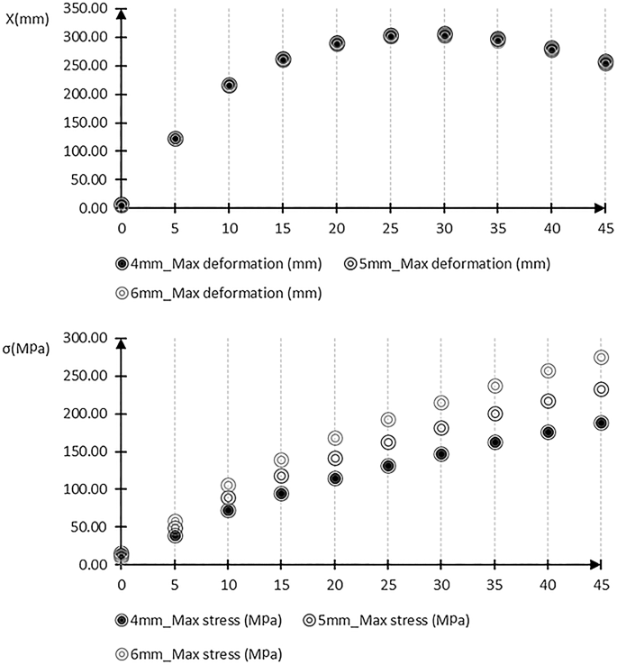
Maximum GFRP plate’s deformation and stress for different relative opening angles of scissor-like elements for 4, 5 and 6 mm plate’s thickness
The findings reveal that the maximum deformation of the plate occurs when the scissor-like elements reach an opening angle of 30 degrees. Furthermore, the maximum stress experienced by the plate increases in direct proportion to the relative opening angle of the scissor-like elements. This emphasizes the significance of considering the structural behavior of the system under its maximum operating conditions. In addition, thinner plates exhibit slightly higher maximum deformations with lower stress values. Consequently, the GFRP plate with a 4 mm thickness was selected for further investigation.
GFRP plate perforation ratio
The perforation possibilities for the GFRP plate have been examined by adopting ratios of 15, 21, 28 and 36% of its total area. The reference GRFP plate has a 5 × 5 hole pattern of 60 mm radius of the holes on its surface, resulting in a 15% perforation ratio. Two approaches are used to increase the GFRP plate’s perforation ratios. The first approach refers to an increase of the number of the holes, and the second approach, of the radius of the holes, while maintaining the 5 × 5 hole pattern. In the first approach, 6 × 6, 7 × 7 and 8 × 8 hole patterns are utilized to achieve 21, 28, and 36% perforation ratios, respectively. In providing an equal plate’s perforation ratio in the second approach, the radius of the perforation holes of the GFRP plate are increased to 72, 84, and 96 mm, respectively. Figure 5 shows the GFRP plate with different corresponding perforation rates.
GFRP plate’s perforation ratios of 15, 21, 28, 36% from left to right
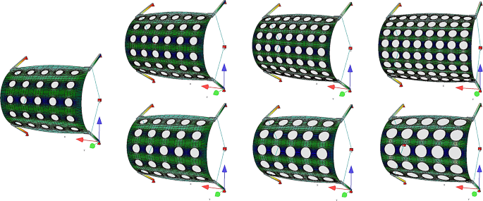
The numerical analysis conducted for the perforated GFRP plate focused on the maximum plate’s deformation and stress for each perforation ratio achieved through the two approaches as summarized in Tables 2 and 3. Figures 6, 7, 8 and 9 present corresponding FEA results.
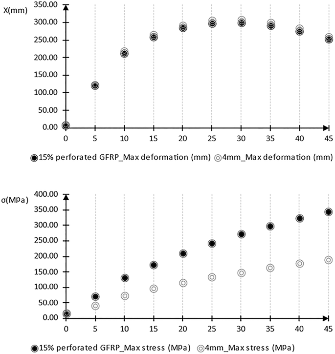
Maximum reference GFRP plate’s deformation and stress for 15% perforation ratio compared to the non-perforated GFRP plate with 4 mm thickness
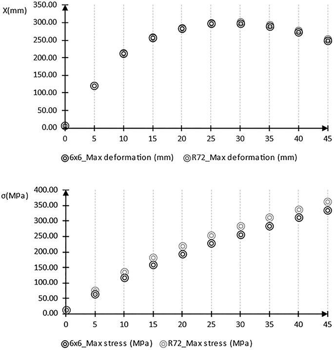
Maximum GFRP plate’s deformation and stress for 21% perforation ratio
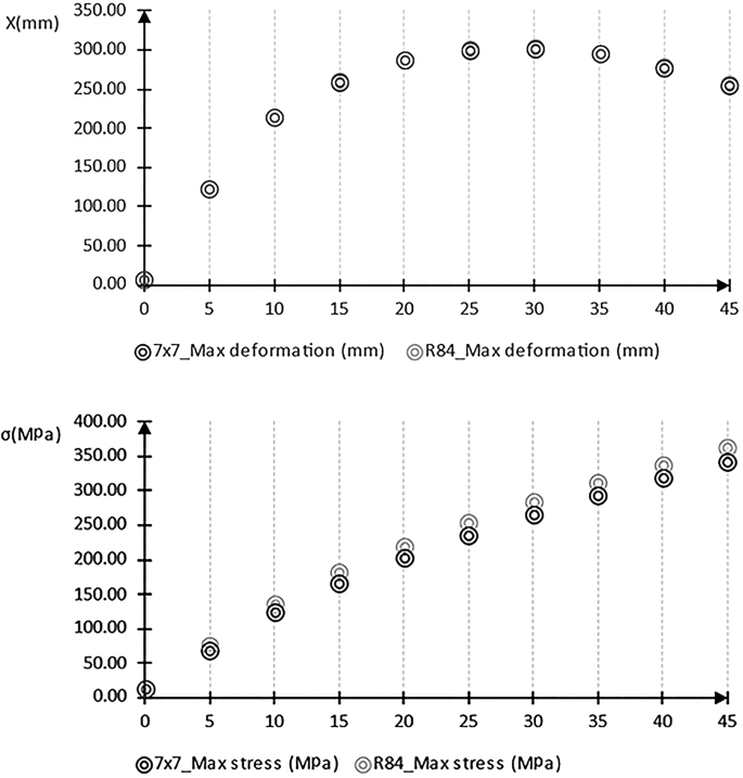
Maximum GFRP plate’s deformation and stress for 28% perforation ratio

Maximum GFRP plate’s deformation and stress for 36% perforation ratio
The findings reveal that the maximum deformation of the perforated GFRP plate practically remains at the same value of approximately 300 mm, similarly to the non-perforated one. This value remains constant at relative angle of 30 degrees of the scissor-like elements. Furthermore, the analysis shows that the maximum stress experienced by the perforated plates are notably higher than the one in the non-perforated plate. However, the maximum stress essentially remains at same values for all examined perforation ratios. Furthermore, the increased perforation ratio achieved through the holes’ radius increase results in slightly higher stress values than the ones in the corresponding perforation ratios achieved through holes’ number increase. In addition, a 36% perforation ratio of the GFRP plate can be achieved without compromising its structural integrity, since the maximum stress values registered are approximately 350 MPa, i.e., significantly lower than the 500 MPa yield strength of the GFRP (Fig. 9).
Conclusions
The present study introduces a novel design concept for a unitized curtain wall system, incorporating integrated sun-shading units. This system employs bending-active GFRP plates, supported by scissor-like elements that are positioned at the corners of the plates. Based on FEA, the structural behavior of the bending-active plate has been investigated. This analysis provides insights into the plate’s form-finding and load-deformation behavior under both actuation and external wind loads. The study findings indicate that the maximum stress experienced by the bending-active plate is directly influenced by the opening angle of the scissor-like elements. It is crucial to consider the structural behavior of the plate under its maximum operating conditions. Notably, the maximum deformation of the plate is registered at an opening angle of 30 degrees. Furthermore, the study shows that a 36% perforation ratio of the GFRP plate can be achieved without compromising the structural integrity of the plate since the maximum resulting stress remains significantly below the yield strength of the material. Further investigation of the system’s load-deformation behavior under incrementally increasing external loading will be considered. The system’s load-deformation behavior will be evaluated by means of stability, maximum deformations and stresses of the GFRP plate. Moreover, with regard to the long-term reliability of the proposed system, a fatigue analysis of the GFRP plate will be conducted to provide more realistic and comprehensive results, as these panels are subjected to repetitive loading over time, especially in dynamic environmental conditions.