Article Content
Introduction
This research is concerned with how to go about the structural reuse of stone in the design for a new house at St Leonard’s Hill, Berkshire, UK. This presents certain challenges, opportunities and points for broader consideration that the paper addresses in four main sections. The first section, Nested Stone Pasts and Futures, considers contextual matters and discusses the dynamics of the use and reuse of stone in the built environment. This includes considerations about the material character of stone and some key cultural considerations. The second section, St Leonards Hill Past and Present, considers the history and current situation of the site of the proposed new house. The lineage of past inhabitation is addressed, including the fate that befell the last house. The site is also understood as a site of re-extraction, a place to excavate previously used material from which to constitute the new house and to source stone for the prototyping. The third section, House Ruin House, sets out the proposed house design as an architectural response to the situation. The fourth section, Stone Reuse Prototyping, is targeted research that asks specific questions around reuse opportunities here, develops a tailored methodology utilising digital tools to enable the research and presents and discusses the resultant prototype. The paper finishes with a short conclusion addressing the research outcomes and their implications for the specific architecture project. Points are also raised regarding the implications of emerging digital methodologies for stone reuse and the use of non-standard components in architecture more broadly.
The general context for this research is that structural stone use in the UK greatly declined in the twentieth century, for complex reasons, and there is now a resurgence in research and design interest in using stone structurally once again. This is because of the inherent suitability of stone for construction and its potential to displace more carbon intensive forms of construction [1], that it was itself displaced by over the last hundred years or so, now that there is an interest in carbon reduction. It is also because of the rich and diverse experiential character of stone relating to its regional material character and provenance. Stone reuse is of particular interest here as something which, on the one hand, is nearly as old as stone use itself [2] and, on the other hand, as a field which is now opening up again due to shifts in priorities, advances in digital methods and also things like the use of post-tensioning that expand the applicability of structural stone.
Nested stone pasts and futures
This section gives some context on stone use and reuse and introduces some key terms of reference and concepts for the research. Stone is a unique and diverse category of material resources for the built environment. It takes solid form and evolves in the ground over timespans ranging from billions of years to just a few years, up to the point of its extraction. At this point it is cut out of the ground and becomes a stone, an artefact, “An object made or modified by human workmanship, as opposed to one formed by natural processes” [3], a part of material culture. From the point of a stone’s extraction onwards, all of its future possible dimension stone (non-composite stone) forms are nested within its original, extracted one. This future might extend to one use, a ‘use’ and a ‘reuse’, or to any number of use cycles and evolutions on its journey through the built environment. On this trajectory, the form of each stone is nested within the originally extracted stone form and all of the previously cut forms, somewhat like a Matryoshka doll. The stone, in its final, diminished, form will eventually return to the earth, turn to dust, or dissolve into the water cycle, or a mixture of these things.
Figure 1 gives a sense of some contemporary stone journeys on the Isle of Portland, UK, on route to their first use. This is an oolitic limestone deposited around 150 million years ago during the late Jurassic period. It is mined by cutting it from its bed with a diamond chainsaw (Fig. 1a), producing large blocks of up to around 8 m3 (Fig. 1b). Mined blocks are typically squared up using diamond wire saws and then the stone building component is cut from this block in a subtractive process. Figure 1c shows nested diamond wire cutting of structural column segments, and Fig. 1d shows some cut column segments ready to be finished prior to dispatch to site for assembly. At each stage through to the completion of the stone building part, some of the stone is shed and this may be returned to the ground or put to another use. The utilisation factor, the proportion of stone contained in the final pieces compared to that in the quarried stone from which they were cut, varies widely and can typically be less than half. A simple way to describe the process from ground to inhabitable architecture is ‘extract-subtract-assemble’.
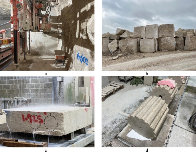
Working with Portland Stone at Albion Stone Ltd a) Quarrying the stone with a chainsaw b) Quarried blocks c) Nested diamond wire cutting of column segments a squared d) Cut column segments
A matter of particular interest in this paper is the cycling of stone during reuse and, in this case, further steps are added to the stone’s journey. A shorthand for this is ‘extract-subtract-assemble-inhabit…disassemble-(subtract)-assemble-inhabit…disassemble-(subtract)-assemble-inhabit…’ and so on as the stone cycles through the built environment on multiple use cycles. The ‘(subtract)’ stage indicates that the stone may be recut for reuse or simply reused as it is. Considered in the context of circular economy principles, current practices and emerging frameworks [4,5,6,7], the material character of stone sets particular dynamics and constraints on what is possible regarding stone cycling. Constraints include those relating to the nesting of future forms withing past and current ones, as noted above. This also applies to other materials formed via subtractive processes, such as timber. When considering the 3Rs, ‘reduce, reuse, recycle’, stone can be subject to reuse ‘as is’, or to recutting giving a form of subtractive reuse. Recycling in the case of dimension stone would typically indicate downcycling-type processes involving crushing the stone for uses such as landscape works or as aggregate for concrete. Within all of this, entropy [8] is irreversibly at work, via the use and cycling of the stone and the natural weathering processes to which the stone is subjected over this time, on route to return to the natural environment with higher entropy, in a more complex and dispersed form. Stone cycling can slow that trajectory, and the rate of entropy increase. This can hold the stone in the human use cycle for longer, reducing the pull on newly quarried stone and other construction resource extraction.
How reuse plays out for any particular building stone is highly contextual, influenced by a whole range of matters, ranging from stone geology and weathering to human culture. Stone reuse has been the subject of extensive study, much of it falling within the notion of spolia (for example, [9, 10]). This term is derived from the Latin word Spolia which means spoils, and examples of stone reuse include stones have been taken as the spoils of war and displayed as trophies, a point of national pride (for example refer to [11]).
Spolia is a rich and divergent field and so it is helpful to be specific about the types that are of interest here. Given stone’s durability and heavy weight, historically, when a stone construction project was underway it was common practice to grab as much stone from the immediate vicinity as possible, to limit the need for quarrying and transporting virgin stone to site. Figure 2a is an example of this form of expedient reuse, the reuse of historic column segments in the Byzantine defensive wall at Chania, Crete. Reuse of building stone as is can be cumbersome to incorporate but can bring the benefit of 100% utilisation of the reused stone.
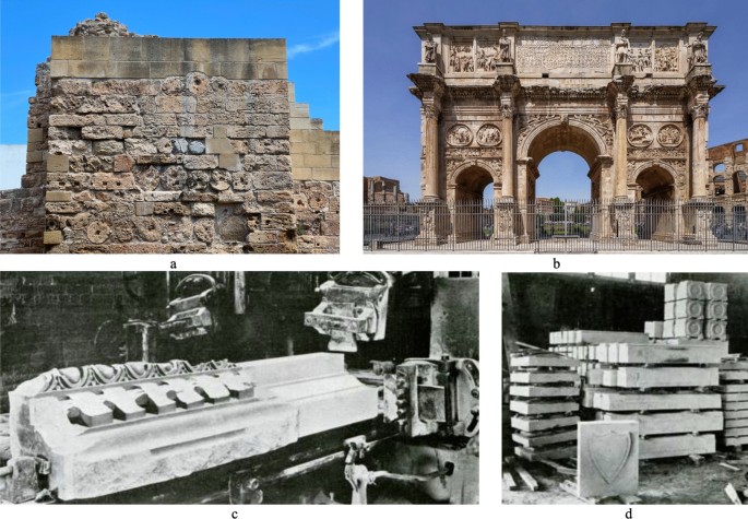
Relevant types of spolia a) Expedient reuse of stone column segments in the Byzantine defensive wall, Chania, Crete b) Artful reuse of stone in the Arch of Constantine, Rome, 4.th century [12] c) & d) Recutting reclaimed Indiana limestone building stones in 1920 [13]
There are many examples of spolia where there is an artful reuse of building stones in ways that are carefully tailored to carry forward aspects of material culture, including the decorative character and meaning of the stones, in a way that contributes to the form and language of the new work of architecture. A well-known example is the Arch of Constantine (Fig. 2b), constructed in the third century CE using columns, friezes, sculpture and other stones reclaimed from a range of other architecture from different eras dating from the preceding two centuries. These stones are reused with some targeted recutting and can be understood as a light form of the ‘(subtract)’ stage in the model described above. This gives a rich and seemingly cohesive architectural language collaged together from the stones from preceding eras, giving a work of architecture that is rich in the cultural heritage that it carries forward, but not in a way that is deferential to the original form and purpose.
A more recent example of spolia, dating from 1920, is pictured in Fig. 2c&d. Here reclaimed building stone is recut to give ‘new’ stone from ‘old’. This is a building-as-quarry approach, whereby the reclaimed stone is fair game from which to ‘(subtract)’ any shape of building stone that the architect and design team desire. The material culture of the’old’ stone is predominantly carried forward on its surface and this is deleted when this surface is cut away to reveal the ‘new’ stone within. The benefit of this approach is that reclaimed stones can potentially be used to make forms that don’t closely correlate to their current ones. This means that reusing stone in this way can displace quarried stone and reduce extraction. It also makes this approach broadly applicable today, when the design methods used by architects and the design team do not typically account for the form of a stone before cutting, but rather it is understood more as a commodity to be shaped as wished. The recut stones will have a crisp, ‘new’ appearance which is typically what is wanted from stone at present. This is at a time when stone is often used as a non-structural, ‘luxury’ finishing material, thinly cut into tiles, panels and slabs for use as wall cladding and linings and floor tiles.
So, the different spolia approaches identified here – expedient reuse, artful reuse and recutting – come with different implications and have been, and will be, applicable in different contexts. Key considerations include those relating to resource efficiency and broader cultural considerations including those relating to architectural form and aesthetics.
St Leonard’s Hill past and present
The remaining sections focus on a particular case of stone reuse at St Leonard’s Hill. The hill rises to around 85 m above sea level near Windsor in Berkshire, UK, with panoramic views of the surrounding landscape and Windsor Castle to its east. Figure 2 shows how it looked in the early nineteenth century. The site has been occupied for millennia, with evidence that it was once the site of an iron age fort. It has previously been a place of pilgrimage and the site of a royal hunting lodge. In recent centuries, it has been the site of several large country houses owned by various aristocrats and prime ministers. The general source of the historical information in this section is the report Historic Background and Development of St Leonard’s Hill [14].
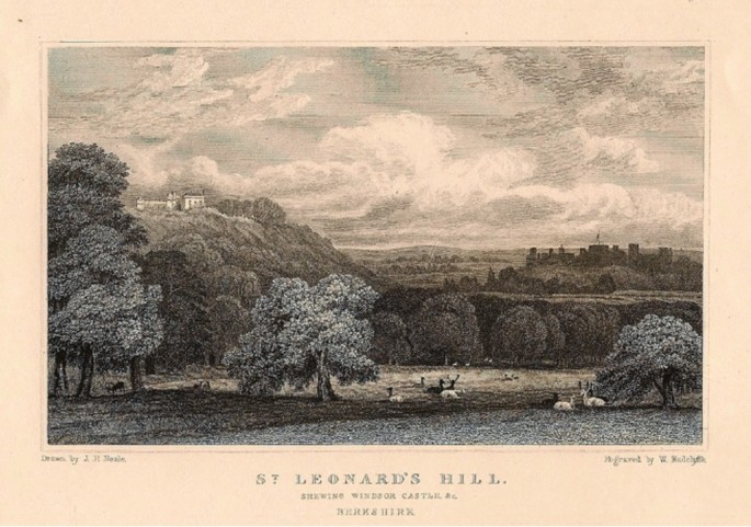
St Leonard’s Hill, on the left, with Windsor Castle on the right. Drawn by J.P. Neale and engraved by W. Radcliffe, 1818
A large house on the site was bought by the Dowager Countess Waldegrave and then largely rebuilt by her in the 1770 s to a design by the architect Thomas Sandby (Fig. 3). In the 1870s Sir Francis Barry effectively rebuilt the house as a much larger and slightly gaudy mansion in the style of a French Chateau (Fig. 4a), to a design by architect Charles Howell. This was a substantial mansion, built with stones including British sandstone, perhaps some of it from Cefn Coch, Wales, and grey English ragstone, a hard type of limestone.
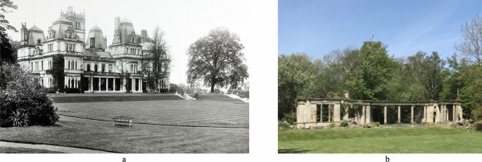
a The St Leonard’s Hill house dating from the 1870 s. [15] b The ruin today
Sir Francis Barry died in 1907 and when Lady Barry died in the 1923, the estate was sold off into several lots and when the house failed to sell it was demolished with dynamite by their son soon afterwards. This was at a time when many English country houses were being lost, brought down by a combination of factors including falling estate incomes, rising costs and the impact of death duties at the point of inheritance [16]. Mr Reg Try acquired the site of the house ruin in 1940, around 40 acres in total, and all that remains of the old house today is the rather beautiful stone portico (Fig. 4b). This is surrounded by some large, ornate building stones that would have formed a part of the classical language of the original house. The broader site is a reconstituted landscape incorporating spoils from the rest of the house. Numerous piles of stones and mounds of bricks dot the site, running to at least several hundred stones and many thousands of bricks in total. As many of these have been lying around for a century now, these areas have effectively returned to nature. The stones have acquired a certain character from their recent history, including broken corners, dirt, mosses and lichens (Fig. 5).
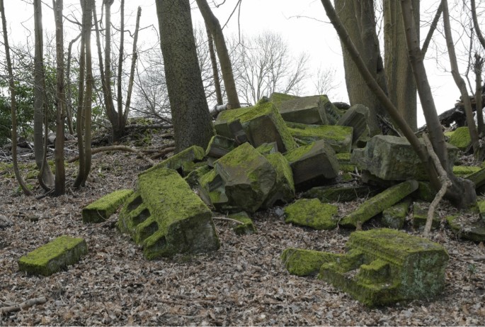
A pile of building stones in the surroundings of the demolished house at St Leonard’s Hill. Photographer: David Grandorge
House ruins house
This section briefly describes the broader architecture project for a proposed new house on the site, commissioned by Mr Andrew Try, the grandson of Mr Reg Try, as a context for the stone reuse prototyping. The design development method has involved a kind of quasi-archaeological process of creative reconstruction, of reimagining the ruins. This has been an exercise in developing the new house plan on the footprint of the ruined house, encompassing what remains, including portico and foundations. The result is a plan with a sense of a familial relationship to the historic house, an overlapping taxonomy built on shared foundations Fig. 6.
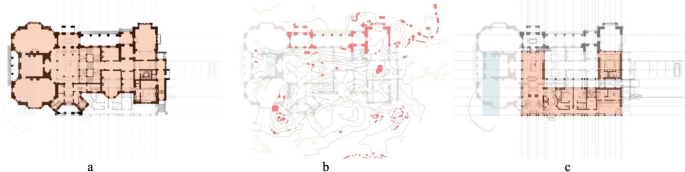
a) Plan of the original house, circa 1875 b) Site with ruins circa 2015 with the original house plan superimposed c) Plan of proposed new house with the original house plan superimposed
Additional to the new house interrelating with the old and encompassing its ruins, a key opportunity identified early on was the potential for reuse of the building materials and components from the old house that are now scattered around the site following the house demolition and the activities since. This is a particular example of circular material resource systems in the built environment. The materials to be reused here, principally building stones and bricks, are already present on site, having fallen out of human use a century ago at the point where the previous house was demolished. They have lain here as a fresh layer of archaeology, in a tell-like configuration, up to this point, when they are now to be drawn back into the human use cycle. This gives a house-ruin-house sequence for this particular type of circular material flow.
The house design includes the proposed construction of a structural stone frame recut from the available stones on site and integrating the remaining portico structure (Fig. 7a). The frame is partly reinforced and considerations regarding how to cut the new stones from the old are addressed in the next section. This stone upper ground floor is built off a structural brick lower ground floor, constructed partly with bricks reclaimed from across the site (Fig. 7b). Many of these were broken by the demolition process and so there has been a separate study on how best to lay these broken bricks.
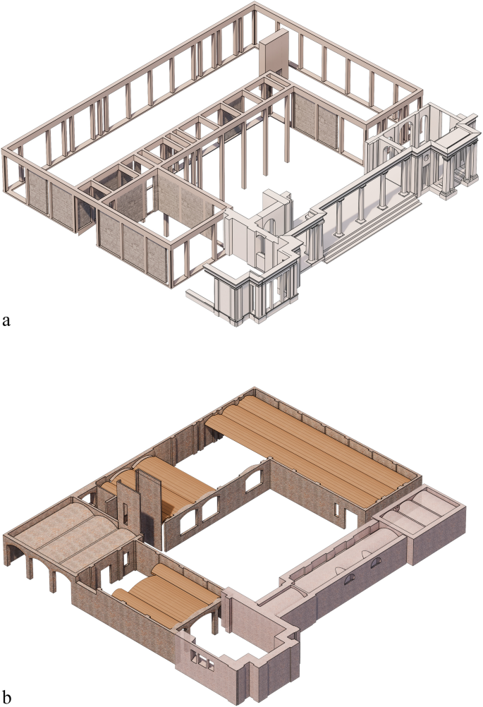
An exploded axonometric drawing of the two stories of the new house, with a) reused stone for a structural stone frame to the upper ground floor, integrated with the remaining portico structure and b) reclaimed bricks used for loadbearing structure to the lower ground floor, combined with some vaulted timber
There is a playful enjoyment in the bringing together of old and new in the overall character of the house that can be seen in Fig. 8a, with the remains of the old house adding a rich character and carrying forward aspects of cultural heritage relating to the previous inhabitation of the site. This mixing of old and new is an established mode of practice in England, going in and out of fashion over time. An historic example is Old Scotney Castle in Kent [17] and a recent example is the RIBA Stirling Prize winning Astley Castle in Warwickshire [18]. This type of approach opens up broad opportunities for how to evolve our existing architecture in ways that can carry forward some of the existing richness and accommodate more environmentally sustainable approaches by cycling material. As a part of the project, the existing foundations are being reused and incorporated into the substructure for the new house (Fig. 8b).
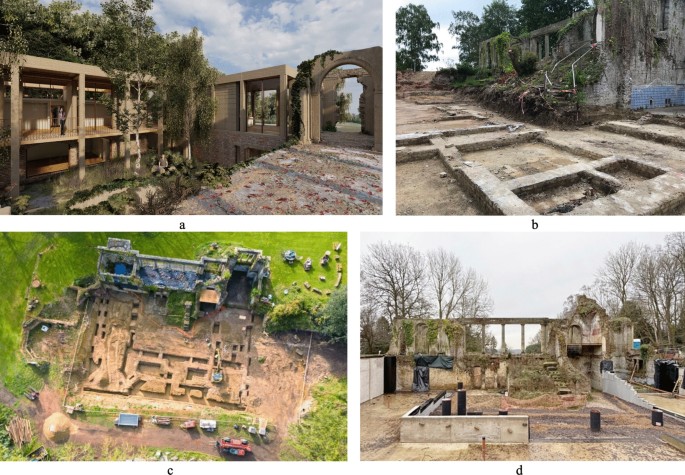
a) Visualisation looking from the portico across the courtyard garden to the new entrance colonnade at upper ground level b) The existing foundations uncovered. c) Ground works excavations undertaken around existing foundations. Photographer: Bow Tie Construction d) Construction work in progress, lower ground floor slab cast and utilities below ground services runs and ducting installed, 2024
Stone reuse prototyping
As noted, the intention of the exercise is to reuse building stone available on site at St Leonard’s Hill in the construction of the new house. Several questions arise in relation to this. What stone reuse approach might be applicable in this case? Recutting is the broadly applicable method due to the house design and accounting for the available stone, and a basic form of artful reuse is also explored. What methodology might enable the architect and design team to design this stone reuse for the new house? What an experienced stonemason will ascertain in seconds, from just looking at a stone, regarding its capacity to accommodate new stereotomy, an architect will not. And the stones are currently piled up on site, far from view, some distance from the architects’ office. How can digital tools help enable a viable design workflow here? And what might the outcome be in terms of architectural character and aesthetics? A prototype stone portal has been created as a means to address these questions and get a sense of viability and character.
Organising, capturing and cataloguing the stones
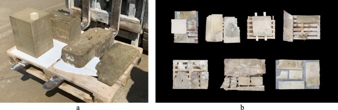
As stones are currently scattered across the site, the first step in the methodology was to locate and select some suitable stones and gather them together. A number of sandstones were selected that had broadly suitable geometries to constitute the prototype portal design described below. Collection was done with the aid of a telehandler (Fig. 9a). The stones were then cleaned and placed individually on pallets (Fig. 9b) to make them easier to move around and to help facilitate LiDAR scanning. Each stone was individually numbered to help keep track of then as distinct artefacts (Fig. 9c).
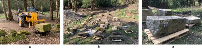
a) The gathering of selected stones for the prototyping b) The collection of stones c) Stones are individually numbered
Following collection and preparation, the first LiDAR scanning of the stone area was then undertaken using a Faro Focus 330 × 3D Scanner to create a point cloud of the topsides of the stones (Fig. 10a). The stones were then individually turned over and further scanning was undertaken to enable their undersides to be captured. This captured the complete stereotomy for each stone in several scans and then data for each stone was digitally isolated, cleaned, and painstakingly stitched together to create individual stone digital twins. This stitching process was undertaken in CloudCompare, using the point pairs picking feature, and utilising the reference targets that were manually painted onto each physical stone. Each stone had approximately 5 to 7 reference targets along their flipped edges to allow for the two halves of the 3D scanned stones to be referenced together into a final, single model for each stone. This process automatically generated numerical deviation reports for each reference marker, and when numerical outliers appeared, they were isolated or removed from the reference system, but this process was also further verified visually to check for consistency in the final combined point cloud geometry. This resulted in a sufficient level of confidence regarding the accuracy of the resultant digital stone model geometries with regard to the proposed use of the stones. Figure 10b shows the stones assembled on Rhino as a digital inventory of around 64 stones in total, the resource from which to create the prototype portal.
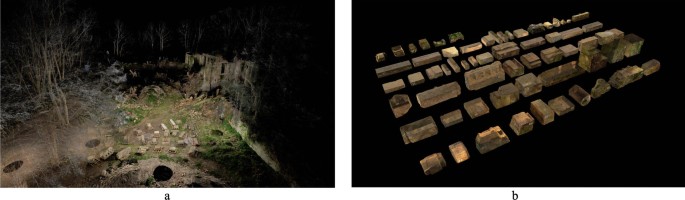
Capturing and cataloguing the stones a) A LiDAR scan of the collected stones on site b) A Rhino model with all of the stone collected together to form a digital stone inventory
Digital design workflow
Once the digital inventory of stones was created, it became possible to manipulate these on digital platforms and to develop the design, using readily available digital design tools including Rhino. There was some time-consuming work to do here, including transforming the data from point cloud models into more useful surface models. Due to the method of capture, and the need to combine two different data sets of the LiDAR scanned stones, for top and bottom faces, automatic meshing within the scanner software Faro Scene wasn’t possible. Keeping the information in a point cloud format was the most optimal form to verify accuracy and visual characteristics. As mentioned, alignment of point clouds for individual stones was undertaken in CloudCompare and the resultant aligned point cloud was then meshed in Meshlab. This was verified for accuracy between point and mesh (surface) geometry. After the generation of this surface geometry, a subsampled mesh was generated to increase the ease of use of each individual stone. This involved decimating the digital stones from roughly one million vertices each down to around ten thousand.
The on-site 3D scanning methodology was designed with a focus on high resolution and accurate data capture. It involved a total of 42 scans, 21 scans for each orientation of the stones, and took just over a day to complete. A more effective digital workflow for this scale of prototype could focus on faster methods of data capture, through various 3D scanning phone applications or photogrammetry workflows, but this would then also produce information that was more prone to error or incomplete captures and would most likely require further post-processing and post-capture interpretation. Similarly, automatic point cloud to point cloud alignment processes could also be used to avoid the need for target markers on the stones, but these are somewhat prone to error on partial point-clouds. Overall, the methodology deployed aimed to develop a workflow that could be scaled up effectively, to scan larger quantities of stones, at which point LiDAR 3D scanning could be more time effective then scanning each stone as a discrete element in its own right.
Alongside the creation of the individual digital twin for each stone described above, a specific portal from the house design was selected for the purposes of developing a full-size prototype (Fig. 11). This consists of a gateway column, forming one of the main entrances to the house, a regular column and a regular lintel. The house design includes some steel reinforcement to enable the use of stone to create these forms, and this is reflected in the prototype design.
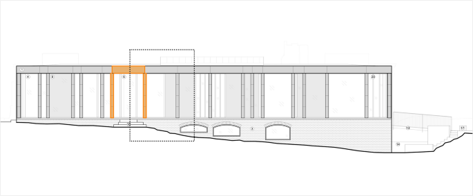
The North elevation of the house indicating the prototype portal location, including a gateway column in orange, a regular column and a regular lintel
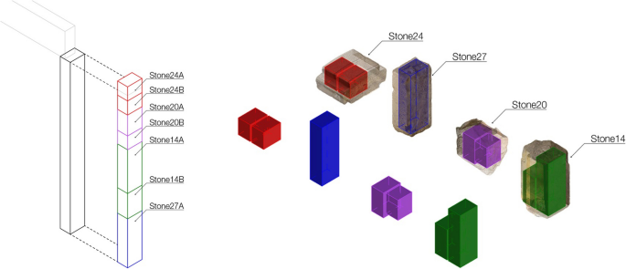
It then became time to consider how best to use the stones to create the portal. Utilising the digital twin of each stone, an exercise was undertaken to get a sense of what portal profiles could be nested within it, and so recut from it (Fig. 12). The digital twins also made clear the ornate character of some of the stones and made it simple to calculate the amount of stone that would need to be cut away to reveal the new stones.
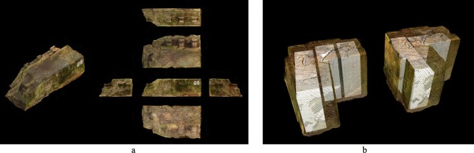
a) A layout to show the geometry of one of the stones b) Testing out what portal forms could be nested within a couple of the existing stones
An approach was adopted to use stone profiles of differing lengths for the lintel and columns to get maximum utilisation from each existing stone. An exercise was undertaken on the applicable stone digital twins to give a sense of the utilisation factor that could be achieved with the relevant stones (see Table 1) and this indicated that utilisation of just under half of the stone would be possible, with a little more than half ending up as offcuts and slurry when using the stones for the recut lintel and column parts.
Figure 13 illustrates the final portal design. An approach has been adopted of clean recutting for the lintel and regular column and the opportunity to investigate a simple type of artful reuse has been taken in the design of the gateway column. Here, there is a playful, irreverent approach of bricolage, where there is no attempt to utilise the architectural ornament in the role it originally played in the architectural language of the previous house, such as to form part of a cornice. Here it is used to add detail, complexity and richness to a column that would help to signify a main entrance to the house, in a somewhat baroque manner. It is also a way to carry forward some of the character and heritage of the previous house and the subsequent ruin.
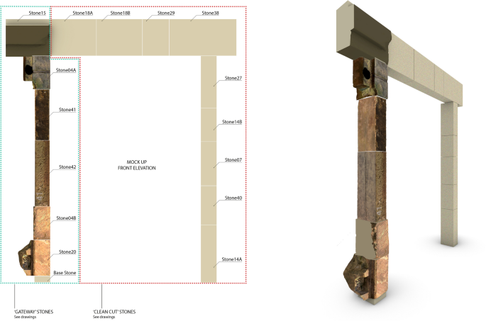
Elevation and 3 d view of the new portal
One of the considerations during the development of the prototype was what type of representations to use to explain the proposal to various parties. A part of this was producing drawings that would enable the stonemasons to cut the new stones from the existing ones in the intended arrangement. Figure 14 shows a drawing produced to explain how the new stones nest in the old when clean cutting the stone for the regular column. This is a fairly simple matter of showing the orientation and nesting arrangement of new stones in old and the arrangement of these stones in the column. Consideration has been given to stone bedding orientation for cutting and assembly of the prototype, including with regard to structural and weathering performance. As the stone is under relatively low structural stress, the approach adopted here is that the at the grain can run in either orientation, horizontally or vertically. This gives the benefit of enabling maximum stone utilisation through efficient nesting of new within old geometries. Any stones with particularly pronounced and open grain were discarded before being cut. This appraisal was done by the stonemasons, with some stones discarded, and some additional stones were included in the batch transported to them to cover this eventuality. This approach is being been further considered and developed for the stonework design of the main house.
Drawing produced to show the arrangement for cutting and assembling the stones for the regular column
The design of the cutting and arrangement of the stones that were only partly recut for the gateway column was a more in-depth and time-consuming process. This was partly as it was an intuitive process without a clearly defined aesthetic at the start and so it was a matter of trying different arrangements and then evaluating the results. This involved considering the aesthetic, the way in which the design carried forward the material culture of the existing stones, and what the case may be for this or that arrangement. In this instance, through trial and error and many iterations, a quasi-Classical arrangement emerged. Ornamental stones were cut and reused to articulate a clear notion of a column base and capital, and plainer stones closer in size to the required structural cross-section of the column were chosen for the main shaft, hence these needed no cutting to their four visible sides. It is anticipated that this process would become quicker as the aims here become more firmly established, and there are examples of the type of character intended. Explaining the cutting requirements for these stones also required more detail than the recut stones, because of the need for each cut to have a precise relationship to the existing form, to give the intended outcome, for example see Fig. 15. This approach naturally increased the utilisation factor of the stone, as less stone was being cut away, with over 60% of the stone being reused for the gateway column.
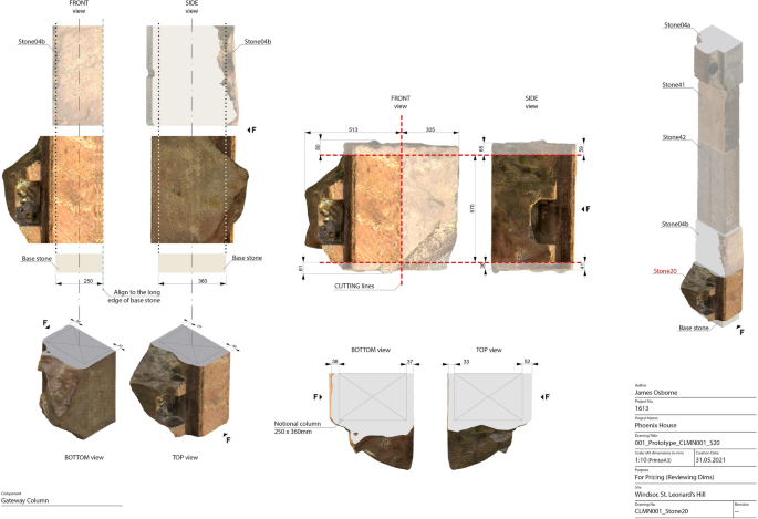
Drawing produced to show cutting arrangement for the stone at the base of the gateway column
Cutting and assembling the prototype
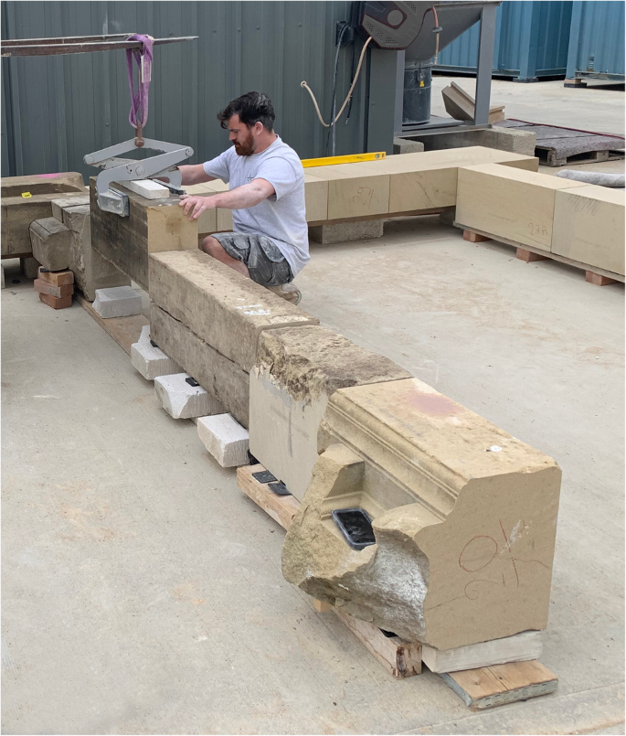
After the design was completed, stone cutting and assembly commenced at The Stonemasonry Company, the stonemasons for the prototype. This physical prototyping enabled the testing of the viability of the methodology and it also, importantly, gave a physical artefact that could be appraised by the client and project team. Due to its unusual nature, it was hard to get a true sense of the character of the portal when it only existed as a digital model. This work commenced with the marking up and cutting of the stones using a CNC bridge saw (Fig. 16). This was a fairly manual process as the appraisal, marking up and setting out of the stones on the saw was all done by hand before the CNC cutting took over. Cutting of the partly cut stones required more careful set up as stones had to be placed in precise orientations in relation to the blade to give the intended result, as compared to the looser fit of the nested recut stones.
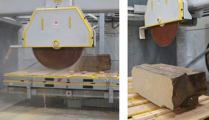
A stone being cut on the CNC bridge saw at The Stonemasonry Company
The cutting generated quite a lot of waste stone (Fig. 17), as anticipated, and some separate work has been undertaken on how to incorporate this into the broader design for the house, including as a part of the landscaping. The intention here is to utilise as close to 100% of the stone as possible within the scheme design, with a cascade of recut parts. Some of the stone is turned to slurry during the cutting process and the potential to reuse of this has not been studied here.
a) A freshly cut stone and offcuts b) Composite image showing pallets with the waste from several stones, alongside some of the freshly cut ones
When the stone cutting was complete, the arch was assembled horizontally in a dry lay arrangement (Fig. 18), to assure a correct fit prior to drilling for reinforcement and then assembly. The stones were then drilled and reinforced to componentise the relevant structural elements, lintel and columns, (Fig. 19) and to give the tensile performance required for the house design. Webb Yates, the structural engineers for the prototype, initially designed steel reinforcement in the form of 12 mm diameter rebar, fully grouted, to the centre of each column and to the top and bottom of the lintel, to cope with the relatively low tensile forces. In the prototype as built The Stonemasonry Company included reinforcement in the form of post-tensioned steel cables, for reasons of expediency (as they are experts in post-tensioning).
Dry lay of the stones to check fit prior to assembly
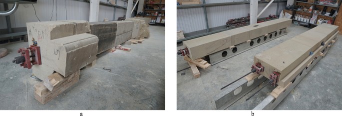
Reinforcement of a) the gateway column and b) the regular column, left, and lintel, right
Once formed into the structural components, assembling the portal was relatively quick and straightforward (Fig. 20). When comparing this type of reinforced construction to non-composite structural stone, this makes it harder to reclaim the stones for individual reuse cycling, and easier to reuse as the complete structural elements, beams and columns, that they have been formed into. Some reinforcement and post-tensioning also enables a broader range of architectural typologies due to the addition of tensile performance, which gives far broader applicability to current architectural forms.
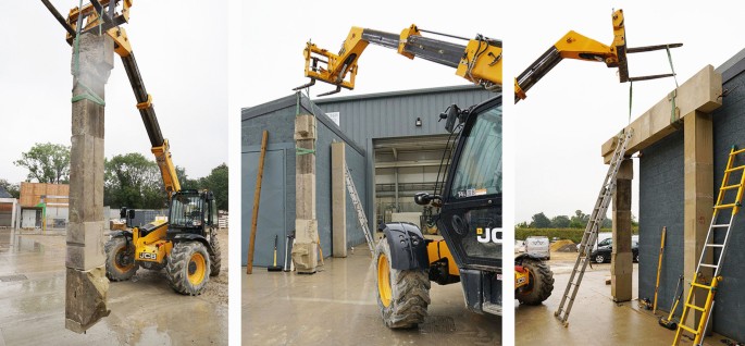
The stone columns and lintel/beam being assembled into the portal
Figure 21 shows the final stone portal as installed at the stonemason’s yard. The clean-cut lintel and regular column demonstrate the viability of this approach for the project. The artful reuse of stones in the gateway column clearly displays the stone’s provenance in as it relates to the history of the site and adds considerable richness to the aesthetic. There is also richness to the character when experienced in person that cannot be conveyed in a photograph, a physical relationship that is not just visual, a sense that you may want to lean up against this column whilst surveying the landscape or nest your coffee cup on it whilst talking to a friend. It proved somewhat more time consuming to design and partially recut stones in this way. As mentioned, this is expected to speed up with practice, and it would also be possible to design an algorithm to partly automate and speed up the process. This could be done, for example, using specific geometric nesting add-ons in Grasshopper such as Galapagos. Macro commands could be created to automate the processes for generating meshes from point clouds and then generating subsampled geometries. If such a process was merited, due to the scale of the data captured and the project, then it is important to highlight that this could only speed up the initial nesting process, and that there would still be important aesthetic and spatial judgements required to determine the final nesting arrangement and geometry for each recut stone. When considering the partial recutting of stone more broadly, there is an economy of means to this approach, it is a way to cut less and get more. Less recutting is involved, which will save some energy and related carbon emissions. The resultant stones carry forward aspects of material culture and weathering from their past lives. More stone is carried forward, keeping the horizons of all possible future forms a little broader than would have been the case with clean recutting.
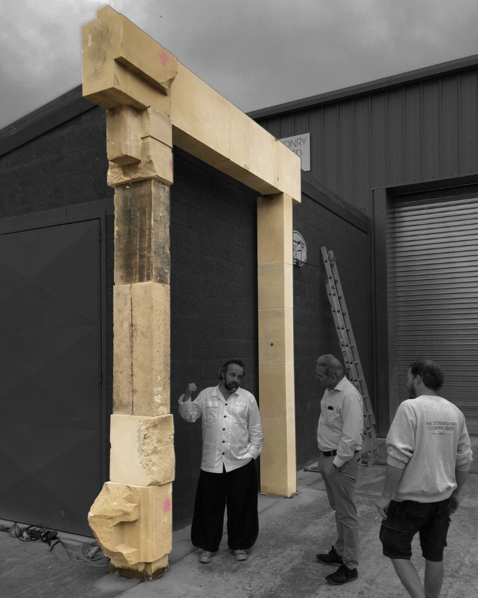
The final stone portal, with contrast adjusted to emphasise the portal form
Conclusion
This research has developed and tested a digital design methodology for reusing stone at St Leonard’s Hill, within a broader methodology spanning from stone collection to assembly of the prototype portal, as summarised in Fig. 22. This is understood as a tailored and unusual ‘…disassemble-(subtract)-assemble-inhabit…’ loop for these stones, after they had lain scattered and disused across the site for around a century. The methodology has been established as a viable way to enable the reuse of stone on the site for the main house project, which is currently proceeding. The physical prototyping has given valuable insights into the visual and material character of a trabeated portal from the house design when created using this approach. It was received positively by the client and design team, more so than the digital model that was hard to appraise. The partial recutting of some of the stones has given a rich result and has also been quite time consuming to design. This has, in some regards, been a case of taking more time to carefully design something that then requires less cutting, saving carbon and material resources through the reuse of stone on site via partial recutting. As outlined, ways to streamline and speed up this process include the development of a tailored algorithm that could partially automate the process. Whilst this was not necessary at this research stage, it could make the methodology more broadly applicable and readily scalable.