Article Content
Introduction
Background
The construction sector is responsible for 11% of global greenhouse gas emissions [1], and, in Europe, for 84% of material extraction [2] and 37% of waste generation [3]. Generally made of steel and concrete, the load-bearing structure of buildings accounts for up to 45% of buildings’ embodied carbon, of which the slabs are the largest contributors [4,5,6,7]. Researchers have investigated various strategies to lower the embodied carbon of building slabs [8]. One strategy is reducing concrete and steel quantity in slabs by either optimising conventional systems [9] or developing new thin floor systems, for example, inspired by historic ribbed or vaulted systems [10, 11]. Bio-based materials are also gaining interest, for example, in rammed-earth and timber hybrid systems [12]. A little-explored pathway for load-bearing floor design is reusing elements salvaged from deconstruction sites.
Building waste, particularly discarded concrete, is an untapped source of alternative materials for building structural floor systems [13]. Concrete waste accounts for 30% of the total solid waste in Europe [14]. These quantities are expected to rise as demolition activities are still increasing [15, 16], and concrete accounts for nearly half of the mass of all European buildings built after 1949 [17]. Today, buildings are demolished at an ever younger age [18] and often for reasons related to urban, economic, or social dynamics [19, 20]. Thus, structural elements of buildings deemed to be demolished are potentially in good condition [21] and present a sufficient remaining service life to be salvaged and reused into new structures [22], supporting a more circular use of existing resources. Therefore, this paper investigates new design avenues for load-bearing floors made of reused concrete and steel elements that have the potential to vastly reduce waste generation, natural resource consumption, and upfront embodied carbon.
Reusing discarded steel elements rather than recycling them can significantly reduce the embodied carbon of steel structures [23]. Examples of structures built from reused steel elements have dotted the construction history, such as the industrial buildings that reused the steel structure of Max Bill’s Swiss 1964 National Exhibition pavilion [24]. Steel has previously been reused to build load-bearing floors in combination with another material. For example, salvaged steel beams have been combined with reclaimed wooden joists to build the Villa Welpeloo’s load-bearing floor (NL) [25]. In the K118 extension (CH), the load-bearing floors have been made of reused steel girders topped with a new reinforced concrete slab [26].
Reusing reinforced concrete (RC) is a little-known circular approach to efficiently valorise discarded concrete [27]. Reusing concrete elements differs from recycling concrete, but the two approaches are too often confused. For the recycling approach, concrete structures are crushed into aggregates. Then, these crushed aggregates replace a share of natural aggregates in new concrete mixes, called “recycled concrete mixes”. The production of the “recycled concrete mixes” still requires newly extracted sand and gravel, water, and fresh cement in similar or slightly higher proportions. Because of the fresh cement needs, “recycled concrete mixes” have similar embodied carbon to mixes with natural aggregates [28]. Unlike recycling, reused concrete elements are not crushed but carefully extracted from obsolete structures. Large structural elements are extracted, generally using a circular saw (Fig. 1a), lifted and stored (Fig. 1b, c,d). The carefully extracted structural elements are then reused as is or only after minor preparation into a new structure. This paper solely focuses on the reuse of carefully extracted reinforced concrete elements.
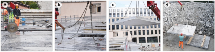
The extraction process from soon-to-be demolished structures of RC elements for reuse: (a) sawing, (b–c) lifting, and (d) storage before transport and direct reuse in a new project after minor or no transformation
Past examples of concrete reuse have been documented since the late 1960s [27]. Most examples reuse precast elements, as the pre-existing connections between the distinct precast elements ease their disassembly and reassembly. On the other hand, reusing pieces extracted from cast-in-place structures is rarer as the monolithic nature of this type of RC structure makes them less trivial to dismantle into elements and reassemble. To the authors’ knowledge, projects that have reused flat elements extracted from cast-in-place structures work mainly in compression, hence only reutilising the compressive strength of the concrete, like a stone [29, 30]. Conversely, to valorise the structural capacities of discarded RC structures at their best, this study explores how to reutilise the compressive and tensile strengths of flat saw-cut RC elements. Through the design, supply, construction and assessment of a prototype, this research introduces a new way to build low-carbon floors by reusing flat saw-cut RC elements in bending and combining them with reclaimed steel profiles. Recent work by the authors conceptually and analytically studied the potential of reusing flat saw-cut RC elements in new floor systems [13]. However, detailed design projects and full-scale experimental validation are still missing. By designing, supplying, building, and testing a full-scale prototype of a new floor system made of reused steel and concrete, this work contributes to advancing knowledge in the emerging domain of concrete reuse, developing ultra-low-carbon construction systems, and extending the field of design possibilities with reused components. To the author’s knowledge, the prototype presented in this paper is the first known built application of a floor system made of reused steel and reused cast-in-place concrete elements.
Objectives
The goal of this paper is to design in detail and assess a new floor system that reuses RC elements in bending through a full-scale prototype. The detailed objectives are (i) to develop in detail a new floor system; (ii) to verify the technical feasibility of the system by designing and constructing a full-scale prototype, named FLO:RE, with elements salvaged from local demolition sites (Fig. 2); (iii) to assess the structural and environmental performances and the circularity of the system by testing and analysing the prototype.
Methods and materials to design the floor system, build the prototype, and assess the system are presented in Sect. Methods. The system conceptual design, the prototype detailed structural design, the construction process and the load-test and environmental assessment results are presented in Sect. Results. These results are discussed in Sect. Discussion, and conclusions are presented in Sect. Conclusion.
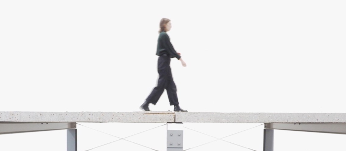
FLO:RE prototype for an office building floor: a 30-m2 prototype made of reused steel profiles and saw-cut RC elements salvaged from nearby demolition sites
Methods
Overview
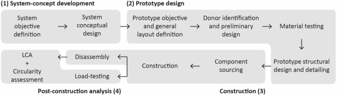
Section Methods presents the four-step methodological framework to achieve the paper’s goals (Fig. 3). First, Sect. System conceptual development method describes the methods used for the system concept development (Step 1). Next, the approach used for prototype design (Step 2) is described in Sect. Objective and general layout definition and Prototype structural design method, which introduce the prototype objectives and the design methods, respectively. Then, Sect. Construction method introduces the construction method (Step 3). Finally, the methods used during the post-construction analysis (Step 4), namely a structural load test, a Life-Cycle Assessment (LCA) and a circularity assessment, are described in Sect. Load-test procedure, Environmental-assessment method, and Circularity-assessment method.
Methodological framework
System conceptual development method
The first step is the conceptual design of a new load-bearing system through an iterative design process. The main objective is to design a load-bearing system that reuses RC elements while meeting current structural requirements, lowering detrimental environmental impacts of floor construction, being fully circular, i.e. made of reused elements and designed to be reusable, and most importantly, targeting abundant types of demolished structural components. An essential design goal is to reutilise the pre-existing structural properties of the reclaimed elements at best, i.e., to limit downcycling (structural reutilisation aspect). In addition, to increase the application range in new projects, the design should adapt to different spans of the new structure (span-flexibility aspect). To guarantee full circularity, the system should offer the possibility to take the elements apart without damage (dismantlability aspect) and to reassemble them in a different load-bearing floor layout during a subsequent use (future-adaptability aspect). Another project-management objective is using only widely available tools and a minimal number of construction steps to build the system, thus reducing costs (construction-simplicity aspect). Similarly, the deconstruction procedure should be optimised for widely available tools (deconstruction efficiency aspect). Through an iterative research-by-design process, the conceptual design of one of the systems theoretically introduced by the authors in recent work [13] is further investigated and improved.
Prototype design
Objective and general layout definition
The prototype aims to design, build, and assess a load-bearing floor portion of a hypothetical office building in Switzerland made with reused elements and to verify its compliance with all Swiss code requirements for new construction. The floor design follows the newly developed floor system (see Sect. System conceptual development method and System design) and combines reused steel and RC elements. A live load of 3 kN/m2, as defined in the Swiss standard for office use [31, 32] and a superimposed dead load of 2 kN/m2 for the screed, flooring and ceiling are considered. Horizontal loads (wind and seismic) correspond to what the code would consider for a 10-m high building in Lausanne, Switzerland, with 150-m2 floors and a flat roof [31, 32]. The equivalent lateral loads from both seismic and wind effects are then reduced proportionally to the prototype size, i.e. 30 m2. This results in a lateral load of 11 and 56 kN for wind and seismic effects, respectively. For the seismic load, the seismic microzonation of Lausanne is considered.
The prototype involves four RC slab elements placed over three main reused steel girders supported by steel columns. The specific element dimensions and material properties are determined given the selected donor buildings (see Sect. Prototype structural design method). The structural system that is considered in the design involves RC slabs reused as simply supported elements lying on steel girders. No composite action is considered between the RC and steel elements. Action effects (such as bending and shear) for steel profiles (primary elements in the structural system), as well as unidirectional RC slab elements (secondary elements), are thus straightforward to calculate as a function of reused element dimensions. Even if no composite effects are conservatively considered for the structural design, the connection detail ensures a diaphragm effect between RC and steel elements to guarantee horizontal loading resistance.
Prototype structural design method
Once the general layout and objectives are set, the prototype design stage is divided into three sub-stages (Fig. 3): first, the pre-design and donor identification; then, the material testing; and, finally, the final design and detailing. The following paragraphs chronologically describe these sub-stages.
The pre-design and donor-identification sub-stage starts with defining a set of properties for the elements to be extracted from yet unidentified donor structures. These properties include the element types, dimensions, and conditions.
Regarding the RC elements, only existing flat slabs that have not been exposed to weathering and do not present corrosion signs are considered. For transportation and construction ease, it is concluded that the width of the RC element should be a maximum of 2.5 m, and their weight should not exceed 4.5 tons. Their material properties – which are verified at the next sub-stage through a series of measurements – determine their structurally allowable reusable length. Nevertheless, if a first estimate must be done for project-management reasons before these measurements are conducted, a procedure to estimate the maximum RC element spans presented in [13] can be used at this stage. This estimation procedure is based on hypotheses derived from existing-structure assessment standards, such as to the Swiss standards for existing structures [33] and former RC-structure standards.
Regarding the steel elements, only profiles that are not corroded and do not present fatigue cracks or significant deformations are considered. The steel profiles should be I- or H-shaped profiles with a minimum length of 5 m. The requirement for the steel-profile section dimensions is later adjusted depending on the dimensions of the reclaimed RC elements that define the action effects on the profiles.
Once this property set is defined, potential donor buildings are identified among buildings deemed for demolition or transformation. During this identification phase, their structural dimensions are verified with on-site measurements, and their conditions are first assessed through visual inspection, following the method developed by [21]. The complete reusability assessment of the identified donor buildings is out of the scope of this work, and only the material properties of the specific elements extracted for the prototype are assessed, as described in the following paragraphs.
Once donors are selected, the second sub-stage defines the existing material properties. For preliminary design and initial estimates of the stiffness, bending and shear capacities of the elements prior to deconstruction, conservative hypotheses on existing-element material properties are made based on the year of construction, former Swiss RC codes at the time of the construction (i.e [34])., and current Swiss codes for existing structures [35, 36]. Nevertheless, these hypotheses must be verified through measurements with in-situ, non-destructive, and destructive methods, as is commonly done when assessing existing structures [37].
The steel yield strength of the profiles is determined through two types of hardness tests (Vickers and Brinell) and tensile tests following ASTM standards [38,39,40]. For each beam type, two hardness specimens, one from the web and one from the flanges, and four tensile coupons, two from the web and two from the flanges, were tested. The concrete compressive strength is tested non-destructively in 9 locations with a rebound hammer [41] and destructively with compressive tests on three 75-mm-diameter cylinders [42]. The Young’s modulus of the concrete is also obtained from the cylinder tests. The steel-reinforcement bar yield strength and Young’s modulus are determined through tensile tests on four bar samples extracted in the openings. The steel reinforcement bar layout (spacing, diameters and cover thickness) is measured on-site through local openings in the concrete cover and later verified on the cut faces of the extracted RC elements.
In the last sub-stage, the final dimensions of the prototype elements are determined using the updated material properties, and the connection details are designed. The final reused-RC-element span is determined to ensure all structural requirements of current construction standards are met. Design guidelines for determining bending and shear resistances and deflection of reused RC elements have been proposed in [43] and are followed in this study. The main attention point is the partial anchorage of the cut steel reinforcement at the support, where the RC element was saw-cut. It reduces the structural resistance of the element at this location.
Construction method
The construction step is split into three sub-stages: sourcing the reusable elements, assembling the prototype – including preparing elements, and finally carefully deconstructing the prototype. The sourcing of the elements includes their separation from other structural elements, their extraction from the structure, and their transportation to the new site if not already on the future-project site. As recommended by Devènes et al. [21], visual inspections must be conducted before and after element transportation to localise eventual new damages. The elements are then prepared to be assembled. Additional trimming is performed, and connection details are prepared. The prototype is then constructed similarly to a prefabricated structure. Once all data from the built prototype have been collected, the prototype is carefully deconstructed, and its elements are again visually inspected before being stored for subsequent use.
Post-construction analysis
Load-test procedure
Static load tests with loading comparable to serviceability conditions are performed. An identical fifth reused RC element is placed above each slab, resulting in an equivalent to 3.7 kN/m2 if assumed uniformed load. This is slightly above the permanent serviceability load-level conditions. Deflections at supports, steel girder midspan, and RC-element midspan are measured with eight linear variable differential transformer (LVDT) sensors, measuring the element’s vertical deflection. The static load test was repeated four times by moving the load – i.e. the fifth slab – over each of the four RC slab elements.
The load test should demonstrate that only elastic deformations occur and that they remain within the code limitations. If significant uncertainties on the structural capacity of the reused elements remain, load testing until failure can be performed on the elements. For instance, the bending and shear capacity of a reused RC slab specimen can be verified in a 3- or 4-point bending test setup.
Environmental-assessment method
The upfront global-warming potential (GWP) of the system is quantified through a process-based Life-Cycle Assessment (LCA) [44, 45]. The functional unit is the construction of a square meter of an office-building load-bearing slab. System boundaries begin with the donor-building demolition (C1-C4) and end after the new floor construction (A1-A5) [44]. A cut-off allocation approach is used [46]. The GWP impact factors are taken from the Swiss KBOB database [47] and provided in Table A1. The impact factors are representative of the average of the production and recycling chains of the Swiss market. On-site measurements and information provided by sawing companies are combined to approximate the GWP impact related to concrete sawing, drilling and lifting.
The LCA compares the system with a conventional continuous flat RC slab as flat slabs are the predominant floor system in Switzerland. Flat slabs feature inherent advantages, such as compactness, construction ease, and limited costs, that are beyond the scope of the LCA. The flat slab used for the comparison is designed based on Swiss standards, using C30/37 concrete and B500B steel for the reinforcement. The continuous slab is 22 cm thick, with an assumed steel reinforcement ratio of 1.5%.
Circularity-assessment method
The circularity assessment aims to quantify and discuss the use of materials regarding efficiency and resource conservation over multiple use cycles. Circularity is assessed from the point of view of both past and future uses of the construction elements. Upstream reuse, i.e. the use of reclaimed elements, is discussed using (i) the ratio of reused elements over all materials employed in the system, (ii) the ratio of actually reused elements over the quantity of harvested components, and (iii) the ratio of the structural capacity over the action effects, which measures the level of structural reutilisation. Downstream circularity, i.e. the reusability of elements in future use cycles, is assessed by (i) identifying the damage on elements after prototype disassembly (dismountability) and (ii) discussing the possibilities of re-combining the elements in new layouts during future use cycles (future adaptability).
Results
System design
This section describes the new floor system design. The implementation of the design objectives mentioned in Sect. System conceptual development method are hihlighted in italics. The results of the design, construction, and testing of a full-scale prototype are presented in subsequent sections.
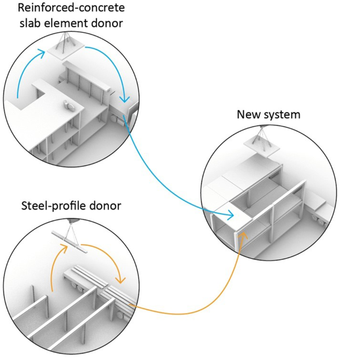
The new load-bearing floor system: a combination of reused RC slab elements (blue arrows) over reused steel profiles (orange arrows)
The new load-bearing floor system is made of two abundant types of demolished structural components: reused RC elements saw-cut in existing flat slabs deemed to be crushed down and salvaged H-shape steel profiles (Fig. 4). For optimal structural reutilisation, RC elements are reused in bending, making the contribution of the existing steel reinforcement to the bending resistance essential. The RC element length is set to reuse the donor structural capacities as fully as possible, and the H-shape steel profiles are optimal for (re-)use as girders.
Regarding construction simplicity, the system requires only widely available tools (regular lifting equipment, standard drilling machine, and regular steel-work equipment). Regarding construction steps, the assembly requires only mounting the elements and bolting the RC elements to the steel girders. Steel girders must be prepared (trimming, connection preparation with drilling and welding, painting). For the RC elements, the only preparation step is drilling holes for the bolts. In addition, to support deconstruction efficiency, RC element dimensions are set to minimise sawing and lifting operations while matching a regular truck width (2.5 m) and existing lifting equipment weight allowance.
For span flexibility, RC elements are installed between steel-profile girders so that floors can span longer than the length of the RC elements. Often found in long-spanning industrial buildings, it is expected that steel profiles are long enough to match most new building spans. All RC elements and steel girders in the system are flat, linear elements that can be resized if needed and rearranged in new layouts. Resizing of the RC elements would however be dictated by the existing steel reinforcement layout. Dry reversible connections are designed to ensure dismountability so that elements can be separated without damage. After dismantling, the possibility of trimming the recovered elements and rearranging them in new layouts remains, which thus supports future adaptability.
Prototype structural design
Before entering the detailed structural design of the prototype, the prototype general features are introduced. The FLO:RE prototype is 30-m2 large with a 5-m main span (Fig. 5a) and is designed as an office-building floor. The prototype combines four reused saw-cut RC elements (3 × 2.5 m) and three steel-profile girders (5 m) that were sourced in buildings undergoing demolition or deconstruction in the region where the prototype is built (Fig. 6). For practical and economic reasons, the six vertical supports of the floor prototype – columns – were designed shorter than they would be in a real building, using steel-girder cut-outs.
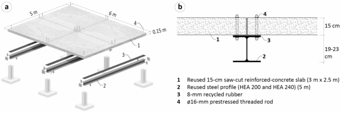
(a) Prototype dimensions and (b) connection detail
The structural design is based on material-property test results, as presented in Table 1. The combination of 15-cm slabs on top of HEA200 (190-mm high wide-flange H standard steel profile) and HEA240 (230-mm high wide-flange H standard steel profile) sourced from two selected donor buildings in Switzerland (see Sect. Reused-element sourcing), and the connection detail (Fig. 5b) were structurally verified using the methods presented in Sect. Prototype structural design method. The bolted connections between the slabs and the beams were designed to ensure the diaphragm effect of the structural system. The horizontal load transfer from the RC slabs to the beams is ensured by friction, thanks to the prestressing of the bolted threaded rods. The relative displacement of slabs and beams in case of a seismic event was also controlled to prevent the progressive collapse of the building.
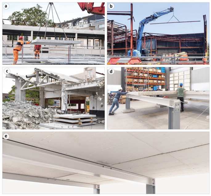
The FLO:RE prototype (d, e) is made of reused RC elements (a, c) and steel profiles (b) salvaged from local demolition sites
The Degree of Compliance (DoCs) of the main structural verifications are presented in Table 2. They all demonstrate reserve capacity of the elements and show that the prototype respects current construction standards. The length of the RC elements was fixed to 3 m, ensuring structural safety for mid-span bending (the critical structural verification in this situation). Deconstruction work had to be exceptionally carried out before all material testing results were available, and the DoC at the preliminary design stage equals 1.05. It is updated to 1.61 after identifying material properties.
The characteristic material properties presented in Table 1 were obtained through the destructive and non-destructive testing methods described in Sect. Prototype structural design method. Table 1 also provides the initial estimated material properties used as hypotheses during the preliminary design phases. The initial material-property assessments were based on old construction standards, and the properties are all conservative compared to the tested ones. The concrete characteristic compressive strength measured with compressive tests on cylinders equals 33 MPa against an estimation of 13 MPa according to Swiss standards for existing reinforced concrete structures [35]. The characteristic steel yield strength measured by the tensile tests on the reinforcement bar equals 499 MPa, against 345 MPa according to Swiss standards for existing reinforced concrete structures [35]. The yield strength of the construction steel of the girders was first estimated at 235 MPa. With tensile tests on coupons, this value was confirmed for the central girder (HEA 240) and could be increased to 275 MPa for the side ones (HEA 200).
Prototype construction
Reused-element sourcing
Figure 7 illustrates the steps to supply and build the prototype. Before the prototype assembly, steel profiles and RC elements were reclaimed from two Swiss industrial buildings deemed to be demolished. Steel profiles were reclaimed from the structure of an industrial hall built in the 1970s (Fig. 7b). Except for some large roof trusses, the whole steel structure was planned for deconstruction as part of a more extensive reuse operation: the steel profiles were separated from each other at their ends, lifted, and stored on the ground. Two HEA 200 and one HEA 240 were reclaimed for the prototype. Visual inspection of the profiles after dismantling localised geometric deformations, essentially resulting from the deconstruction process. Elements were then trimmed to their final 5-meter length while eliminating the distorted parts.
The RC elements were saw-cut from the 15-cm-thick flat roof slab of an industrial building built in the 1960s in cast-in-place RC (Fig. 7a). Following the method described in Sect. Prototype design, the length of the elements was set at 3 m according to the roof slab geometry and structural capacity, and centred at mid-span of the original 3.70-meter span. The element width corresponds to the maximum width transportable on a standard truck (2.5 m). Once the sawing lines were marked precisely by a land surveyor, the donor structure was shored up to ensure structural safety during and after element extraction. The RC elements were then cut out using circular diamond saws. Four M20 wedge anchors were installed in each element to allow the placement of lifting hooks and chains. The elements were then lifted using the articulated arm of an excavator and transported to the assembly site on a regular truck. A visual assessment confirmed the absence of new damage linked to transportation.
For the RC structure, a building pollutant assessment carried out before the demolition work started confirmed the absence of toxic substances. For the steel structure, on-site measurements confirmed the absence of asbestos, and sample testing in the laboratory confirmed the absence of polychlorinated biphenyls (PCBs) but the presence of lead paint. An appropriate removal protocol was defined to mitigate health and environmental degradation risks.
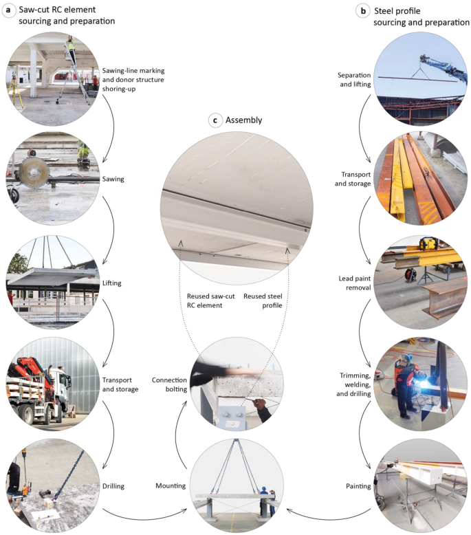
The new system combines reused saw-cut RC elements and reused steel profiles
Element preparation, assembly, and disassembly
The preparation of the steel profiles started with removing the lead paint in the area that requires sawing or welding operations (Fig. 7b). Then, the steel profiles were trimmed to the final dimensions, holes were drilled for the bolted connections, and stiffeners were welded where required. Finally, the profiles were painted in the final colour, chosen to match the existing colour of the concrete sub-surface. For the RC elements, the only preparation step was drilling an 18-mm-diameter hole in each of their four corners for the threaded rod used in the bolted connection with the steel profiles (Fig. 7a).
The assembly (Fig. 8) started with installing and bolting the steel girder on the column heads (Fig. 7c). Then, recycled rubber layers were installed on the girder top flange to ensure continuous contact between the RC elements and the girders. RC elements were then placed on the girders. Lastly, the threaded rods were bolted and prestressed. The 2-cm gap between the RC elements is designed to tolerate reused element geometric variability and is expected to be filled with mortar. This would protect cut reinforcement bars from corrosion.
To test the reversibility of the system, the FLO:RE prototype was later carefully dismantled: threaded bolts were unbolted, the RC elements were lifted and stored, the recycled rubber layer was rolled back, and the girders were unbolted from the column heads, lifted and stored. The prototype was later reassembled and dismantled a second time. Visual inspections of the dismantled elements reported no new damage after these two cycles of assembly and disassembly.
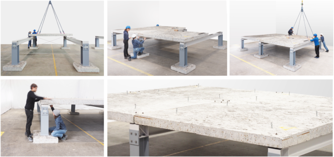
Prototype assembly
Prototype load-test results
Load-test results show predominantly elastic deformations. Moreover, the largest deflection measured is 1.63 mm at the midspan of one of the RC slab elements (Fig. 9c). This is significantly lower than what Swiss standards consider the strictest acceptable short-term deflection (span/500, i.e. 5.4 mm). It is nevertheless acknowledged that due to the stiffness of the concrete slab used to add weight, the applied load may not be uniform and might be concentrated towards the supports, resulting in lower deflection values than if the loading was perfectly uniform. The results thus serve as an initial benchmark, and the small deflections hint towards a partial composite action between the RC elements and the steel girders, which will be investigated in future work.
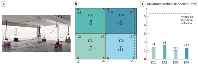
Load-test measurement set-up (a), loading and measurement location (b), and maximum vertical deflection of the RC element (c)
Environmental assessment results
Results of the LCA show that the system has a very small GWP, with results as low as 14.9 kgCO2e/m2 when built 140 km away from the donor buildings (Fig. 10). About two-thirds of this impact is due to the transportation of the reused RC elements. The remaining third is mostly due to the production of the newly manufactured materials: paint (2.7 kgCO2e/m2), steel (1.2 kgCO2e/m2), and recycled rubber (0.6 kgCO2e/m2). Concrete sawing accounts for 0.1 kgCO2e/m2. If transportation of the reused elements is reduced to 20 km, the GWP would be 6,2 kgCO2e/m2. And if reused on site (no transportation), it would be 4.8 kgCO2e/m2.
The computed GWP is extremely low compared to a new flat RC slab made of new or recycled concrete, with reductions of 80%, 84%, 92%, and 94% for 140 km, 100 km, 20 km, and 0 km transportation distances, respectively (Fig. 10). The prototype-based LCA results corroborate that of a parametric LCA computed for more than 20’000 simulated theoretical design solutions, which projected an average 88% GWP reduction when combining reused steel and reused concrete in new floors [13]. The new system also limits waste production and natural resource extraction. Regarding waste production, building 1’000 m2 of floors with the new system avoids downcycling 345 tons of discarded concrete into rubble, generating 23 tons of steel scrap, and extracting the natural resources needed to produce 506 tons of concrete and 25 tons of steel reinforcement, which would be necessary to build a new flat slab. However, the reused system is thicker than a flat slab and implies major challenges in terms of project management.
Nonetheless, the new system sets a new benchmark for low-carbon load-bearing floor construction. As a reference, the GWP of the HiLo floor developed and built at ETHZ, a novel system which minimises concrete use by means of a rib-stiffened funicular floor, is estimated to be approximately 30 kgCO2e/m2 for a main span of 5.2 meters [11]. The GWP of an optimised thin shell floor developed and built at the University of Cambridge is estimated to be approximately 33 kgCO2e/m2 for a 5-m span [9].
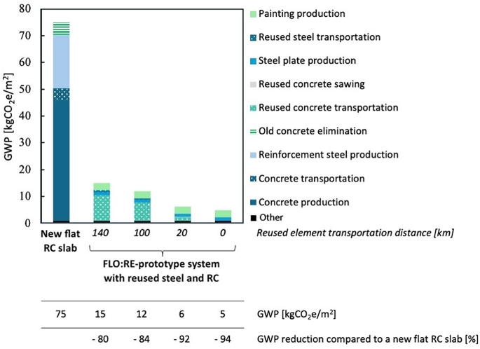
Global warming potential of the FLO:RE-prototype’s system reusing RC and steel and of a new flat RC slab
Circularity assessment
Designed for upstream reuse, the prototype is made with 99% of reused materials in terms of weight. Regarding the use of extracted materials, the RC elements were directly saw-cut and extracted at their final dimensions, thus entirely reused in the prototype. The saw-cut elements are 3 m long, corresponding to 77% of the available donor slab span. The parts of the donor structure that were not saw-cut and extracted were later crushed down and downcycled as concrete rubble and steel scrap. For the steel profiles, elements were extracted at their full original length. After visual inspection, 18% of their length was deemed not reusable because of large geometric deformations, mostly due to machinery shocks during deconstruction. Then, girders were trimmed as they were longer than needed: on average, 72% of the profile length in good condition was reused as girders. Cut-outs of the steel profiles were reused to build the column heads. In more consequential projects where a larger stock would be reused, cut-outs could be minimised using, for example, allocation optimisation algorithms [23, 48].
Regarding structural reutilisation, the system is, to the authors’ knowledge, the first floor system to reuse the bending capacity of RC elements extracted from a cast-in-place RC structure. By reusing the structural capacities provided by both the concrete and the steel of RC, the system moves one step further in the utilisation rate of RC compared to systems where RC is reused only in compression. Based on the initial estimation, the DoC of the RC elements for mid-span is equal to 1.05, meaning that the bending capacities of RC pieces are almost fully utilised (5% of extra capacity). The material property campaign shows that true DoCs are significantly higher, meaning that the utilisation rate could be further optimised if this information is collected early in the design process [21]. Given a continuous bottom reinforcement layout, it would have probably been structurally possible to saw-cut and reuse elements measuring 100% of the available donor span (3.70 m). However, the lifting equipment capacity should be verified, and the transportation plan should be revised since the truck maximum weight allowance is already reached. Regarding the steel girders, structural verifications confirmed that the stock-constrained nature of the design task lead to oversized steel girders. Overdesign could be globally reduced in the future if the reused steel market grows. In the meantime, literature has shown that some oversizing of the reused steel profiles does not prevent environmental benefits compared to recycled steel [49, 50].
Regarding dismountability – an essential requirement for downstream reuse, the prototype was disassembled for the first time after the load test. Visual inspections of all dismantled elements reported no damage. The prototype was then reassembled and disassembled a second time; again, no visible damage or technical issue was reported. In general, it can be assumed that the damage that would occur during disassembly is the same that could occur during assembly. Most damage can be avoided by carefully planning the assembly and disassembly operations, including lifting and storage procedures. However, a systematic visual inspection of the elements before and after these operations will allow most new damage to be identified and the necessary action to be taken. Moreover, micro-damage will be assessed in future work using 3D scanning measurements.
If installed more permanently, joints between the slabs would be filled with mortar. Low-strength mortar would not prevent the separation and lifting of the slabs during disassembly, as demonstrated in past experiences on precast concrete elements [51, 52]. Nonetheless, water jets would be needed to clean the slab sides after the next disassembly. Lime mortars, without cement, would be an interesting low-carbon material to use.
Regarding future adaptability, RC elements and steel girders are flat, linear elements that can be trimmed before a third use. Other arrangements of the dismantled elements in the system with a different span or another structural typology can be conceived and will be subject to future work. At the connection level, despite being theoretically re-mountable, the existing connections require the alignment of the circular holes drilled in the RC elements, recycled rubber layers, and steel girders with a ± 2 cm precision. A connection detail that allows for more tolerance will be developed in the future.
Discussion
Relevance
The presented system is an ultra-low-carbon building floor system that reduces construction waste and natural resource needs and uses the existing properties of widely discarded resources at best. The prototype construction demonstrates the structural performance, the environmental benefits, and the circular material use of the system. The prototype was designed for an office building, but its design could directly be adapted to housing, as it implies lower load cases and generally no longer spans than office spaces. Overall, the development of the system, the demonstration of its technical feasibility through the construction of a 30-m2 full-scale prototype, and the validation of its structural performances, environmental benefits and high level of circularity are an original and needed contribution to the fields of resource and waste management, circular architectural design, and low-carbon structures.
This paper supports that, as long as demolition activities keep happening for reasons unrelated to safety, reusing discarded materials and valorising their inherent capacities at best should be considered a priority. At current demolition and construction activity rates, the potential of reused concrete to reduce the construction sector’s environmental footprint is not negligible. For example, in Switzerland, discarded concrete quantities (6.6 million tons in 2015) are as significant as a sixth of concrete needs (38.8 million tons in 2015) [53]. However, careful deconstruction to extract and reuse RC elements is, with current approaches, more time-consuming and expensive than conventional demolition to crush the concrete as aggregate. Economic and timing pressures make this an obstacle. More investigations are needed to investigate under which conditions this barrier might be overcome. These include improvements to the operational chain, technical innovations and larger-scale economic schemes.
Limitations
The study demonstrated the feasibility of building a floor of 30 m2 for an office building, with a 3 × 5 span. Larger spans could be achieved using longer steel profiles and/or a beam grid. Large-scale applications would require streamlining the extraction and storage process and developing complete validation and certification procedures. New business models and collaborations with prefabrication companies should be explored to ease the deconstruction, assessment and procurement steps. For the application of the system to industrial buildings – that typically imply longer spans and higher loads – the availability of adequate reusable components in the stock of demolished materials should be further investigated. In addition, applicable legal and regulatory frameworks may not be tailored for reuse and might complicate its application [54].
The study is limited to the load-bearing part of building floors. An entire building floor system would be completed with non-structural elements, such as a screed, phonic insulation, flooring, and, eventually, a suspended ceiling and technical installations. How these non-structural elements are designed with a comparable circular design brief is the topic of separate work.
The fire-safety concept for the system builds on the use of fire-proof painting on the steel elements and the existing concrete cover of the reinforcement bars of the RC elements. Nevertheless, future work should investigate the fire performance of the floor system further. Cost analysis on a full-scale project is also planned as future work to complete the system assessment. Finally, more extensive data collection campaigns and investigations would enhance the reliance degree of the impact factors of the new processes.
Compared to a new 22-cm thick flat RC slab, the prototype is built with 15-cm RC slab elements on top of 19 or 23-cm high steel girders spaced every three meters. The additional thickness the girders bring is a potential drawback for real-estate developers as it increases floor-to-floor height. However, if suspended ceiling or technical tubes must be installed below the slab – which is often the case in office buildings – these additional elements can be arranged between the girders. System alternatives where the steel profile would be in the same plane as the RC element could also be investigated.
Designing with reused RC elements presents similarities with designing with prefabricated elements. Compared to cast-in-place RC design, this type of non-monolithic structure requires design efforts at a connection level. Future work aims to extend the set of connection possibilities.
Despite the large quantities of construction waste, the predominance of demolition over careful deconstruction remains a logistic barrier to reusing construction elements. The total and partial absence of resellers for RC and steel elements, respectively, forces design teams of new projects to undertake the identification of a donor building and the negotiation with donor stakeholders. Today, in addition to a lack of professional guidelines for design with reused RC, project phasing is not adapted to these additional phases [21]. Apart from recent policies in a few pioneering territories, the usual phasing of projects is not supportive as it does not allow time for a resource diagnosis phase – in this case the assessment of the structure and RC materials. Furthermore, despite the potential savings made by not purchasing new materials and not paying end-of-life tax, the early economic investment in careful deconstruction is an additional risk for stakeholders. Nevertheless, the authors expect interdisciplinary design and construction teams to be ready to welcome these challenges as catalysts for creativity, ingenuity, and new collaborations. Finally, stricter regulations regarding buildings’ embodied carbon as well as higher carbon and landfill taxes may incentivise the use of low-carbon solutions, including RC reuse.
Conclusion
This paper develops and assesses a new load-bearing building floor system made of reused saw-cut RC elements extracted from cast-in-place RC structures and reused steel girders. The design, supply, construction, and testing of a 30-m2 prototype called FLO:RE led to the following conclusions:
- The original floor system is devised to reuse all structural properties of reclaimed steel and RC elements. One original feature is that saw-cut RC elements are reused in bending, making the contribution of the existing steel reinforcement bars essential to the resistance.
- The prototype construction demonstrates the technical feasibility of combining reused RC elements in bending and steel girders in a new load-bearing structure, using only widely available tools, and in a reversible way.
- Structural verifications using experimentally verified material properties meet all requirements of the Swiss standards for structures. In addition, load tests show the floor-system elastic behaviour and small deflections under load conditions comparable to serviceability conditions.
- The system drastically reduces greenhouse gas emissions compared to other building floors. Its GWP is as low as 15 or 6 kgCO2e/m2 when built 140 km–20 km away from the donor buildings, setting a new low-carbon benchmark and cutting emissions by 80% or 92% compared to a new flat RC slab, respectively.
- The system is a nearly fully circular design. Made with 99% of reused materials in weight, the prototype reuses all the extracted saw-cut RC elements and more than 70% of the good-condition salvaged steel profile length. Thanks to its dry connections, the prototype disassembly demonstrates the reversibility of the system. Flat, rectangular, regular construction elements are expected to be reusable in future design configurations if needed.
Overall, this new construction system opens doors for innovative low-carbon slab designs that reduce waste production, cut natural resource extraction, and are dismountable and adaptable. Findings call for reconsidering reinforced concrete from demolition sites as ready-for-use resources for new sustainable concrete structures. The study also confirms that the remaining challenges include the lack of supply chains and adaptation of design habits, thus calling for more research. As a final point, the authors would like to reiterate that reuse is a palliative solution to building demolition and that reducing demolition should be addressed as a priority.