Article Content
1 Introduction
The advancements of augmented reality (AR) technology offer the opportunity to leverage its benefits to address issues of skilled labour shortage, low digitization, workflow inefficiency and human errors of construction in the architecture, engineering, construction and operation (AECO) industry. AR augments the visual field of the user by superimposing digital information and graphics onto the user’s view; spatially aligned to the real-time physical environment (Nassereddine et al., 2022; Z. Yang et al., 2019). AR head-mounted devices (HMD’s) lenses offer the prospect of hands-free access to important information, instructions, and guidance. This allows for better spatial understanding, improved communication, and more informed decision-making throughout the construction process.
Many prefabricated wooden homes are designed and built specifically to the client (Bartuska et al., 2023), especially in the case of CLT-based designs. The nature of the work requires well-trained, skilled workers to read and understand the assembly plans of the homes. The process often results in lost time studying plans and possible miscommunication from designer to builder. Studies state that an assembly assistance system would be highly beneficial to support workers, both new and experienced to the industry (Haslwanter & Blazevski, 2018; S. Hinrichsen et al., 2016; Tang et al., 2003).
The assembly process in construction applications can be simulated in an immersive and interactive manner through AR-assistance. An AR-assistance system would support human builders and act as a guide towards assembly, thus serving as long-term learning tools. For the potential self-builder or non-professional builder, visual enhancements which can inform and guide them can create a greater ease in the workflow. AR assistance can provide more confidence on the first assembly attempt, where a novice worker with little to no experience in the operation can complete the task with more personalized guidance (Vanneste et al., 2020).
2 Aims and objectives
Increasing urbanization has called for greater demands of skilled labour, efficient workflows and greater quality of work in production-related works, prompting the need for more advanced digital solutions. However, the AECO industry has oftentimes been slow to keep up with advancements in technology (Musarat et al., 2022; Sezer et al., 2021). Technical limitations play a large role, as the dynamic and rough environments of construction sites typical to the AECO sector make it difficult to handle delicate equipment. A lack of awareness and knowledge of the technology leads to poor usability and a large learning curve for implementation, and there are low incentives to adopt new technologies due to concerns of time, cost and resources (Agarwal et al., 2016). Furthermore, as advancements in AR technology are made many commercialized software and toolkits provide advanced and sophisticated functions for AR development. However, the high price points of the tools are not highly accessible.
This paper proposes an AR-driven assembly framework to assist and guide non-professional builders to a CLT-based built scenario. The research targets the necessity for more efficient processes from bringing a design into production, as well as improving digitization in the AECO sector. The AR environment will exhibit a user-friendliness in which a non-professional builder can achieve the desired outcome by: a) developing intuitive assembly sequence steps which acts as an enhanced virtual guide and b) providing virtual models superimposed over the physical objects in the real-time environment using marker-based tracking. It improves upon traditional manual instructions or video tutorials as it provides interactive and dynamic virtual features and projects 3D objects in a real-time environment. Users will feel a great sense of guidance and clarity of the building method through such means. Accordingly, this study expands upon our initial exploration of AR-assisted assemblies for self-builders in an urban village context (Han et al., 2025).
The significance of the paper lies in the target audience of self-builders using AR technology to conduct a building assembly by themselves without guidance or supervision. There is an identified need for non-professionals, such as new workers or self-builders, to quickly learn the building assembly process in a manner that is intuitive and effective. Self-builders may or may not possess knowledge or skill in construction assembly processes, however the AR-driven framework from this research aims to benefit all ranges of skill levels for self-building. For the self-builder, this means that they may confidently participate in the building of their own homes, potentially leading to greater cost-savings, customization, sustainability and self-empowerment in their lives. The authors of the paper argue that AR technology can augment and enhance a self-builder’s knowledge and capabilities in the construction field, and that an individual with no prior experience building a house can conduct the building assembly safely, accurately and effectively.
The following research investigates the question: is the aid of AR technology in assembly scenarios a practical and applicable method to guide a non-expert user to the desired built scenario? The practical implementation of an AR-driven framework for construction processes covers the following areas:
- Improvement of the production efficiency in prefabricated timber assembly processes, namely CLT-based construction;
- Promotion of error-free assembly tasks;
- Creation of hands-on guidance for first-time or non-professional builders;
- Investigation of open-source and accessible tools for AR development.
3 Methodology
The research approach is divided into two phases. Phase 1 is a design phase that consists of the development of an immersive AR environment through the software Unity 2022.3.19f1. Unity (Unity Technologies, n.d.) is one of the leading tools for game development and interactive experiences. Unreal Engine (Epic Games, n.d.) and vvvv (vvvv group, n.d.) are other comparable platforms, however, many third-party hardware and software developers provide AR integrations for Unity through software development kits (SDKs). The AR environment will use Microsoft Mixed Reality Toolkit 3 (MRTK3) (Microsoft Learn, 2023), which includes ready-to-use, user-friendly interaction models. A residential design scheme will be made using Rhino3D and imported into the AR environment as the 3D model. The iterative loop from AR design to AR deployment is dependent on the success of the feature through the Hololens 2, for example if it works correctly, if its orientation is correct, if the interaction features are present etc.
In Phase 2, the environments and models built in Phase 1 will be used to perform a 1:5 scaled assembly with the aid of the Microsoft Hololens 2 HMD. The Hololens 2 possesses beneficial qualities for the use of AR in production, such as advanced sensors to map out the physical environment, computational capabilities and high level of hand, eyes and voice tracking. Furthermore, due to the foundation of Windows support and the Microsoft tools available for AR development, Hololens 2 was the optimal selection for an AR HMD in this research. Following the AR-assisted assembly, conclusions will be drawn based on the criteria of deliverability, constructability and operability (Fig. 1).
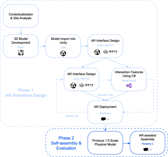
AR framework development workflow
4 Literature review
The assembly process in construction applications can be conducted in an immersive and interactive manner through AR-assistance. It is highlighted by literature that instructions provided through AR technology outperform oral and paper instructions with regard to quality and accessibility (Drouot et al., 2021; Haslwanter & Blazevski, 2018; Mlynarek, 2023; S. Hinrichsen et al., 2016; Vanneste et al., 2020).
Existing research has explored AR use cases in wood-based assemblies. “Human–machine collaboration using gesture recognition in mixed reality and robotic fabrication” investigated the development of a gesture-based AR workflow to facilitate the quality control, fabrication, and assembly of a timber tower (Kyaw et al., 2024). The project uses gesture recognition to pinpoint precise local points of the physical object, enabling the user to register the location of the virtual object in the real environment. The result is a holographic display of the virtual object over the real-world physical object. “Augmented Reality for high precision fabrication of Glued Laminated Timber beams” proposed a precision focused AR workflow glulam beam fabrication (Kyaw et al., 2023). The research used QR code markers for superimposing the digital model in its precise location, achieving drift errors of less than 2 mm for the beam fabrication. The work improves the efficiency and precision of traditional plywood templates for marking connection openings.
Marker-based tracking refers to the technology and process by which an AR system identifies and tracks specific visual markers or patterns within a physical environment. These markers serve as reference points that the AR system uses to overlay digital content accurately onto the real world. Open-source Unity software development kits (SDKs), such as ARToolkit, ARKit and ARCore, allow the hardware to detect the presence of markers and overlay digital content—such as 3D models, animations, or information (Linowes & Babilinski, 2017; Wijesooriya, 2023). Various forms of markers exist, the most popular being ArUco markers, QR codes and 2D image-based tracking.
The existing research focused on the fabrication on local components such as individual beams and modules. This paper demonstrates the potential to leverage AR on a larger scale by looking towards the AR-assisted assembly of the global building system. Further, the discussed projects investigate different wood-based construction such as glulam and timber, while this paper addresses CLT modules. Although the mentioned research demonstrated novel advancements of precise virtual object placement, they primarily focus on projecting static digital content onto the physical surface for assembly and target placement indications. This paper demonstrates a dynamic object tracking system in the AR environment by providing a continuous virtual object superimposed over each physical object in the assembly to simulate a virtual world that is as close to the real world as possible. The researchers believe that the implementation of dynamic object tracking of the assembly components would enhance the user building experience. Commercial software Fologram (Fologram, n.d.) is another popular marker-based tracking tool. It is primarily useful for linking a 3D model design in real time to Rhino. However, these capabilities were not advantageous for the assembly tasks of this project, as it similarly is used for AR projections at smaller scales, and the cost for use of the software was out of the desired range.
“AR-assisted Assembly in Self-Build Construction with Discrete Components” (Y. Li et al., 2023) proposed an AR system for the global building assembly using markerless tracking software, Vuforia (Vuforia Engine, n.d.; Wijesooriya, 2023), for continuous object recognition and tracking. Object recognition refers to the use of image recognition algorithms to identify real-world 3D objects based on their shape and structure and integrates relevant digital information or interactions with them. This allows virtual content to be accurately aligned with the physical object without the use of markers. While markerless AR systems offers a more seamless AR experience, marker-based system provide more accuracy when aligning virtual models in the real world (Kyaw et al., 2023). Whilst Vuforia demonstrates attractive capabilities for object tracking and spatial recognition, they are offered at high price points; Vuforia is also not available in certain regions. The paper seeks to mimic the capabilities of these add-ons through more accessible means, as there are open-source frameworks available which employ the use of QR code and ArUco marker tracking.
5 Methodology: AR-driven framework for production processes
The AR workflow, shown in Fig. 2, describes the process for prompting users to identify and match real-world objects to the virtual object, and follow assembly sequence instructions to complete the production. Videos of the AR environment can be found on Youtube (COIA, 2024).
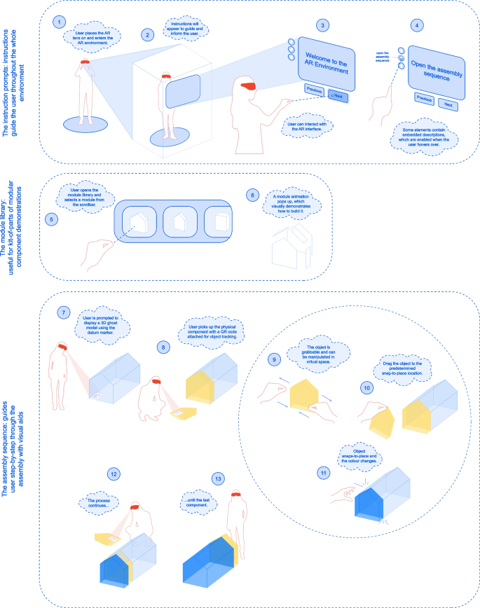
AR workflow diagram
5.1 AR user interface set-up
Many interactable models and actions of the AR environment were provided by MRTK3, including actionable items such as buttons and toggles. MRTK3 models are already configured with user-friendly features such as necessary scripts, colour changes, and sound effects. When advanced and more customized actions were required for the project, custom C# scripts allowing enhancement of the user interface and operability were written and imported into the project.
These features provide guidance for the user through the AR experience. The MRTK3 dialog box is used, which is a text and button prompt for user action (Microsoft Learn, 2023). It displays any desired message text, is customizable with additional buttons. It follows the user’s head movements, in other words, it will always appear at a comfortable distance in front of the user’s head. This ensures that the user will always see the messages during the AR experience. The instruction prompts dialog boxes provide text instructions to guide the user through the AR environment. The user can click the buttons “Previous” and “Next” to display the previous and next instructions respectively.
5.2 Creating a module library
The module library is a scrollbar which holds the building components to demonstrate more in-depth methods to build each component. It is displayed as a library of items where the user can scroll through to select their desired building module. The slider holds cells that may be scrolled through a container of units at a specified number of rows and columns, as seen in Fig. 3.
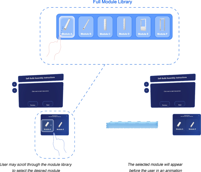
Module library demonstration
In the following AR environment, WikiHouse Skylark 250 building blocks are placed in the module library. This feature is a favourable addition to the AR interface for modular building scenarios, such as the WikiHouse. Scripts were created to demonstrate an animation of the WikiHouse module exploding and closing to its original location.
5.3 Marker-based tracking setup
A primary goal of the AR environment is to provide the user with the ability to connect a virtual building assembly to the real world. Such a feature allows the user to be better informed of their building solution, ensure higher accuracy when building, and be more efficient. As stated previously, commercial products such as Vuforia, Fologram and Wikitude are state-of-the-art tools which enable precise object tracking and spatial recognition. They offer robust systems for creating a communication line between physical and virtual worlds. However, the price point was not justifiable for the use of this project and this research instead sought open-source frameworks to achieve similar results and to provide an easier access to wider community of non-expert builders.
5.3.1 Generating a ghost model using a datum reference point
The first method to bring the virtual model into the physical world is deploying an accurately sized ghost model, that is, a translucent model that provides an indication of the final built scenario, to a desired location in the real-world environment through a datum reference point. The ghost model will show the user the final built outcome that they are striving to achieve.
The AR environment uses a QR marker as the reference point. Microsoft has adopted the benefits of QR code scanning by embedding its abilities in the Hololens through the use of the Windows Mixed Reality QR code tracking ability (Microsoft Learn, 2024). This feature is beneficial in AR applications as it allows QR codes to input data into the AR environment. In doing so, data can be stored in QR codes, objects can be instantiated at desired locations, and clutter in the environment can be mitigated.
The Hololens 2 comes with the native capability to read QR codes. After the QR code is recognized and scanned, a coordinate system is established at the device’s world-space location. An open-source framework using the Windows Mixed Reality QR code tracking ability, developed by Joost van Schaik (van Schaik, 2023a), was used for the project. The framework is robust, easily adaptable, and requires no start-up costs. Therefore, it was selected for use in this research. Specifically, the “MRTK3MultiQR” branch in the repository was used, which includes a framework for continuous object tracking and integration with MRTK3 (van Schaik, 2021, 2023b).
The QR code tracking reads a QR code payload, which refers to the text data stored in the code. If it matches the payload referenced in the Unity AR application, a marker is placed on it which matches the QR codes size, location and rotation in space. This process is visualized in Fig. 4.
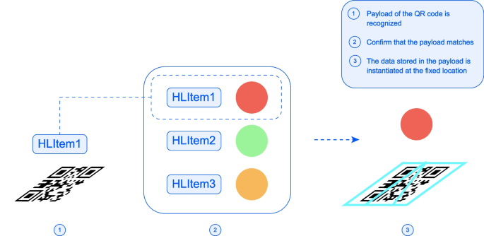
QR code payload recognition to instantiate an object
The process for using the marker to instantiate a ghost model is illustrated on Fig. 5. In Step 1, the Hololens is actively reading QR codes. In Step 2, once a QR code is found, it will instantiate its payload.
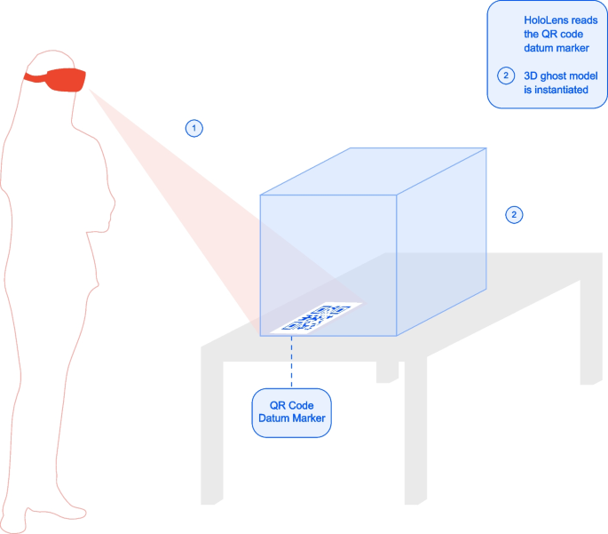
Model display through the Hololens using QR code tracking
5.3.2 Creating an intuitive assembly sequence
The assembly sequence is a feature which walks the user step-by-step through the assembly of the building. Through colour denotations, the builder will understand the next component in the assembly to be placed. It serves as an enhanced visual aid and interactive virtual model to guide the user step-by-step in the building process, similar to an instruction manual.
Based on the button clicked, it will show either the previous, next or all modules in the assembly sequence. The next module target placement uses colour denotations to make it obvious to the user which object is next to be placed. Once the component is placed, it will turn into a dark blue colour, denoting on the virtual model that it has already been secured in place. This process will continue until the assembly sequence is complete, as demonstrated in Fig. 6.

Colour denotation of component placement
Then, the user may move the physical component (along with the virtual component superimposed over it) and be guided to place it in the correct place in the assembly. To place the next component, QR code tracking is used again as a form of object tracking and pose estimation for virtual objects. The QR code tracking is used as a tool for an event trigger to generate a virtual component, and continuously track the virtual object. For each component of the assembly, the builder will scan the QR code on the physical component, which will generate a tracked virtual object superimposed on the physical component. This concept is helpful because it is the most direct method in the AR environment, and it creates a link between virtual and real-world objects. By having the environment continuously scan for QR codes, this capability brings the QR code object tracking as analog to Vuforia as possible. A diagram can be seen in Fig. 7 to illustrate the process.
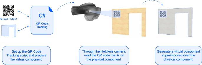
QR code tracking for superimposing virtual objects onto physical objects
A snap-to-place parts feature was added into the assembly sequence, which creates a snap-to-place element in the virtual model. This feature was added to the AR environment to aid the user experience; if the virtual component correctly matches that on the ghost model, when it is in proximity, it will snap to the location on the virtual ghost model. This feature gives the builder reassurance that the component is being placed in the correct location. The feature was based on a training module provided by Microsoft (Microsoft Learn, n.d.). Objects are made interactable in the AR environment (the user can grab and manipulate the object), and they snap to a predefined location once they are within proximity. Lastly, a ray casted from the QR instantiated object to its intended location is created when the QR code is scanned, providing a clear indication to the user on the placement of the scanned object. These two additional features, paired with the continuous QR code object tracking discussed above, creates a solid user-friendly element in the building process. For the user, there will essentially be a sense of a virtual environment being brought into real life.
6 Case study of an AR-assisted assembly
The following section presents the building scheme developed for a case study and the process of integrating the model into the AR environment. Furthermore, this chapter describes an AR-assisted assembly of a scaled model.
6.1 Site context
The urban village of southern China was selected as the speculative scenario to explore potentials for approaching existing site conditions and design problems. The unique phenomenon of urban villages emerged due to unprecedented urbanization engulfing rural settlements on the outskirts of urban areas (Wu et al., 2022; Yuan et al., 2024). These communities face the looming issue of urban gentrification, leading to the displacement of urban village residents and the loss of affordable housing options (Yuan et al., 2024). Despite their informal nature, they play a crucial role in providing affordable housing and diverse employment opportunities for migrant workers and low-income residents (Y. P. Wang, 2021; Wu et al., 2022). Urban village regeneration, referring to revitalizing urban villages while preserving their cultural heritage and social fabric, has been well recognized as having profound impacts to various social groups and urban environments. In addition, it was often found to result in improved land use efficiency and have positive effects on the housing market (L. H. Li et al., 2014).
The design suggests a micro-scale intervention on the flat rooftop spaces of existing low-to-mid-rise buildings, similar to various projects building “parasitic” homes (Gibson, 2019), small houses (Pintos, 2019) and pavilions (Mairs, 2015) atop urban buildings. Baishizhou Village in southwest Shenzhen was selected as the site to design a community of micro-buildings constructed on the rooftop of existing urban buildings. It serves as a self-sustaining community that is connected but independent from life on the ground floor. The buildings proposed may serve as residential homes, small public spaces and service centers. Skybridge connections are proposed to connect the rooftops and their new buildings. It is assumed that a full site analysis has been performed on the buildings and sufficient structural rework and servicing have been completed. Figure 8 shows nine buildings in a three-by-three grid cluster, however the strategy is scalable to as far and as wide as the existing structures allow.
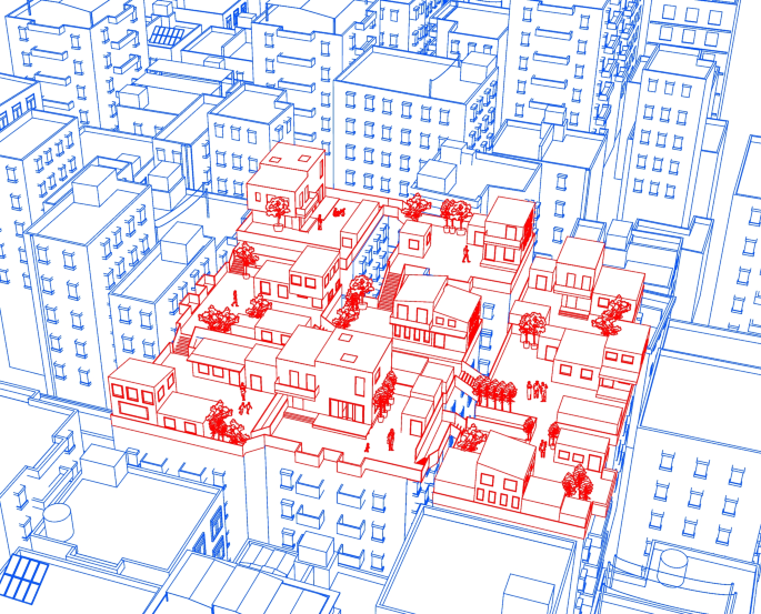
Proposed community of self-built homes in the urban village scenario
6.2 Proposed building model
Both the WikiHouse (Open Systems Lab, n.d.) and CLT structural system (Swedish Wood, 2019) are viable options for a self-build home design, since they offer many modular-like benefits to home-building. Furthermore, their prefabricated nature and lightweight structure make them an appropriate suggestion for the delicate nature of the urban village site. In the following design proposal, a residential building was designed using a CLT structural system. CLT possesses many strengths as a building material, and it is a highly customizable building solution that can be easily deployed on-site (compared to traditional building designs) (Fig. 9).
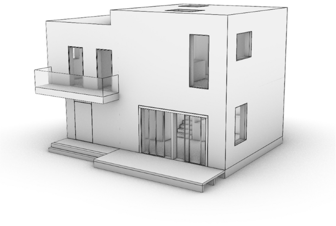
Proposed building model
A section of the building was taken to demonstrate the AR-assisted assembly, as seen in Fig. 10. This section was chosen as it encompasses substantial portion of the building design, including floor, wall, foundation, roof and stair components. The entire proposed building model, scaled at 1:5, was exported as a single object from Rhino and imported into Unity to be used as the 3D ghost model onsite. Following the entire building model import, the components of the building section were imported to the AR environment, to be used as the assembly sequence components.
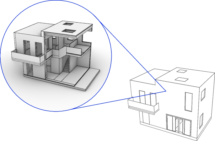
Building section used for the physical model
6.3 Assembly sequence of the CLT panel house in the AR environment
As Unity follows a hierarchy process, the components were arranged in chronological order from the first assembled components to the last. When the assembly components are placed as children objects of the parent with the script attached, the “Previous” and “Next” buttons for the assembly sequence will automatically trigger the next building component to be correctly instantiated in a highlighted color. After the full building model and assembly components are imported, all must be linked to a unique QR code to enable the ghost model generation and virtual object tracking.
Figure 11 shows the assembly sequence for the building section, as it will be configured in Unity. In a 1:1 scale scenario, CLT panel assemblies require heavy-duty equipment, such as a crane and scaffolding, to complete the production. The organization and logistics of the construction sites, along with additional processes and arrangements, are beyond the scope of this research. The assembly sequence does not show the 1:1 scale supports that are required, temporary supports and scaffolding should be used as necessary.
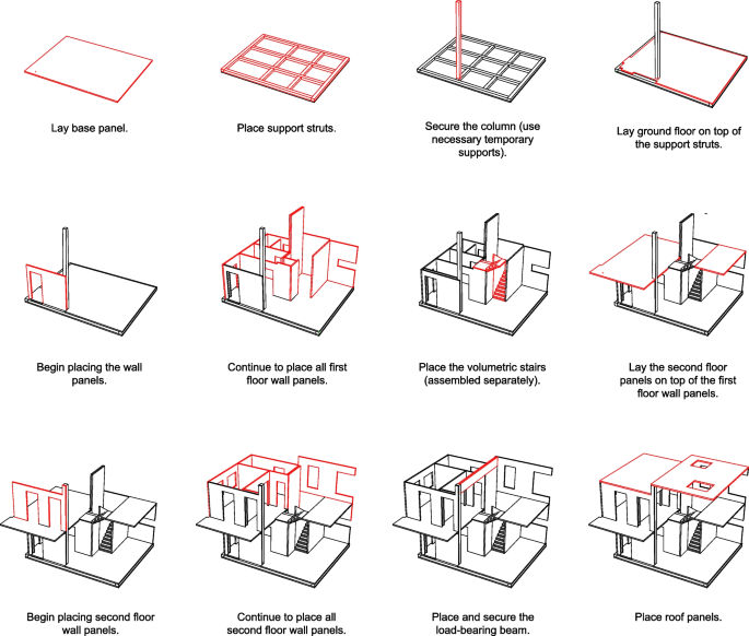
Assembly sequence for the building section physical model
6.4 Scaled physical model testing to demonstrate the AR-assisted building assembly process
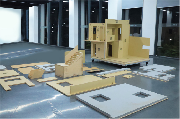
A 1:5 physical scaled section of the building, resulting in a size of 2 m by 1.3 m, was produced to demonstrate the AR-assisted assembly process. The materials used to produce the model are listed in Table 1. A 3-in-1 screw dowel jig connector was used to connect the components, which allows for convenient assembly and disassembly processes.
The AR assembly concentrates on the flat timber-based components. This required a high precision of the dimensions of the manufactured components and coordination of tolerances. Figures 12 and 13 shows the components that were cut for the model section in the virtual model and physical models respectively. Figure 14 shows process photos of the prototype manufacturing and the assembly test.
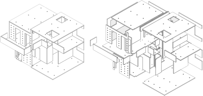
Virtual components of the 1:5 scale prototype model
Physical components of the 1:5 scale prefabricated timber prototype model
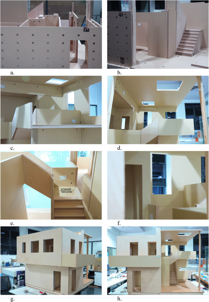
Prefabricated timber prototype manufacturing
Four users were tasked with assembling the prototype with AR-assistance. It is important to note that since a multi-user system has not been developed, each user is in their own virtual environment, simply reflected by what is in their view. During the process of assembly, it was necessary to provide tolerance gaps before final adjustments of the screws and all joints to provide an operable space for manipulating the components. Figures 15 and 16 shows assembly process photos using AR-assistance and Fig. 17 shows the final built model section, assembled using AR-assistance.
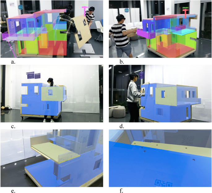
Various assembly processes of the prefabricated timber prototype using AR-assistance
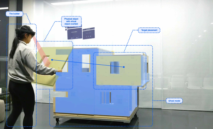
Prototype AR-assisted assembly diagram linking virtual world to real world
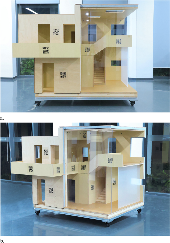
Final built model using AR-assistance
7 Evaluation and limitations of the AR-assisted production process
7.1 User experience evaluation
The 1:5 scale model, of 2 m by 1.3 m size, was found to be instrumental for the validation of the AR-driven assembly framework for production processes. It was observed that some of the sequence steps of the components, due to components’ types of joints (such as flat brackets to joint foam façade elements with their structural load-bearing parts), slightly differ from the expected assembly sequence. For that reason, the AR assembly sequence should be adjusted according to specific user-preferred needs and assembly steps to achieve the deliverability of the prototype. A survey was collected post-assembly from the four users of the AR-driven framework, which quantifies the perception and experience of the builder. The questions were as follows:
- How was the immersive experience of the AR environment?
- How was the user comfort using the AR lens to build?
- How was the operability with the components?
- How was the constructability of the physical scaled model?
- How confident were you carrying out the assembly, using the AR-assistance/guide manual?
- How clear were the instructions and assembly steps shown in the AR environment/assembly guide?
- Was the readability of the QR codes manageable? In terms of distance from user, recognition and any lag time?
- How was the model display through the AR lens?
- How well did you think the AR-guidance/manual improved and enhanced your building experience?
- How well did you think the AR environment assisted with visualizing the building? Was it a good tool for visualization?
Based on the survey results, the questions regarding the user confidence and the visuals provided by the AR environment were ranked the highest. Aspects such as operability with the components, user comfort and clarity of the assembly steps were ranked slightly lower. Lastly, constructability of the model, the immersive experience and readability of the QR codes, were deemed the areas of improvement. This would be attributed to positioning errors with the QR code placement, which would require adjustment. The joinery allowed for convenient assemble and disassemble processes, but could be further refined for better constructability (Fig. 18).
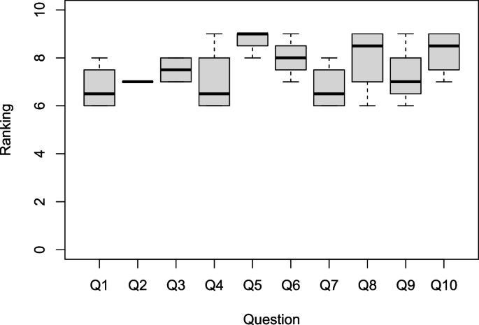
AR user experience survey results
7.2 Limitations
Although there is identified potential in which AR technology can benefit the flow of production, there are a few technical limitations and areas of improvement. At the current stage, the AR-environment is a hard-coded nature of the system, where each component of the entire building must be associated with a unique QR code. This process proves to be very tedious and time-consuming, as well as leaving room for human error. A suggestion is looking towards rising research of machine-learning in AR applications (Apostolopoulos et al., 2022; Saovana et al., 2020), which may provide the potential for machine-learning recognition of particular components.
The integration of QR code tracking in the AR environment was instrumental in creating a two-way interaction system between the user and the real-world environment. It creates a context-aware system, where the Hololens can recognize objects and confirm their location in real time. At the current stage, AR systems prove a reliable source for use as a datum marker, but the continuous tracking feature causes lag in the AR environment. It was stated before that the size of the QR codes play a role in how easily recognized they are by the Hololens. Advancements in HMDs such as lag time of projections and registration speed of QR codes would strengthen the application of AR-assistance in construction scenarios for more precise and durable tasks.
Lastly, the existing framework only allows one person to access the AR environment at once, meaning only one user can operate with AR-assistance. On a larger scale or for more complex and collaborative projects, it would be highly beneficial to integrate multi-user AR experiences in a synchronized building scenario, where the builders are capable to recognize activities provided by different builders in one real-time interactive scenario.
8 Scaling from 1:5 prototype to full-scale construction for AR integration
The purposed of the downscaled prototype 1:5 was to establish a controlled environment where the AR-assisted workflow for human-centered assembly logic could be validated in laboratory conditions, particularly regarding sensitive features such as object tracking via markers and interface responsiveness. This model allowed iterative testing without requiring large-scale logistics or machinery. The following section of the paper describes the benefits of the prototype, the implications and challenges for scaling to a 1:1 scenario, and a strategic roadmap to scaling the model to real-life scenarios.
8.1 Easily scalable components of the prototype
The greatest benefits of the following AR-driven framework are attributed to its easily scalable components. Firstly, the AR user interface’s interaction paradigms (e.g., snap-to-place, task visualization) are software-based and can be directly applied to full-scale components. Secondly, the object tracking pipeline, using marker-based pose estimation, scales in theory depending on the virtual source object size. While precision may vary, the logic and implementation remain consistent. For that purpose, it will be necessary to mark or label prefabricated components with a visible label, for instance, with a CNC-engraved label of the proper size.
8.2 Challenges of scaling to 1:1
The following section discusses the challenges of scaling the framework to a 1:1 scenario. The first is the limited field-of-view of the full AR model due to the close proximity to large assembly components. Full-scale implementation would require a hybrid strategy to accommodate for the limited view, such as workers alternating roles between close-range assembly and distant coordination via AR views. For instance, a leading worker in the control room would be responsible for coordination, having access to the large-scale AR ghost model. Secondly, heavy machinery coordination poses another challenge. Real construction assembly involves large equipment such as cranes, scaffolds, and lifting aids. Each building component itself may also be large and heavy. A solution to this challenge involves developing a communication line between the AR tool and machinery status, such as integrating AR with robotic lift feedback. Therefore, the current developed workflow should be enhanced by recognizing operation machines and their states during the construction process. The last major challenge is the lack of a multi-user environment. The system should be capable of synchronising AR views across users working on the construction site to maintain a consistent digital-physical twin state. Such a system implies real-time model state broadcasting, possibly via a server-client architecture.
8.3 Strategy for scaling
Although our study was limited to a 1:5 scale prototype, it served as a proof-of-concept to test the viability of AR-assisted workflows in prefabricated assembly scenarios, focusing on predefined prefabricated components geometrically identical to the CLT parts. The core components of our system (marker-based object tracking, real-time spatial feedback, and step-by-step assembly guidance) are fundamentally scalable and can be adapted to a 1:1 scenario.
Mitterberger et al. (2020) has demonstrated the 1:1 scale assembly of a brick façade with AR-assistance, however each component (the brick) itself is small, capable of one user holding it in their hand. With respect to prefabricated timber or CLT components, the topic of scaling 1:1 is a different hurdle. The authors acknowledge that full-scale deployment introduces specific challenges, particularly occlusion when users are close to large elements, coordination and work task synchronization between multiple workers, and integration with heavy equipment. These challenges require a hybrid approach where AR-assisted navigation is shared among near-field workers and distant coordinators, supported by synchronized virtual/XR environments.
Future work will include piloting the system in prefabrication factories and integrating AR cues with prospective robotic equipment (such as cable-driven assembly robotic) and heavy lifting systems. We also plan to enhance tracking robustness through machine-learning-based vision methods (recognition of particular components based on pretrained datasets), particularly in cluttered or occluded settings in unconstrained construction sites (Fig. 19).
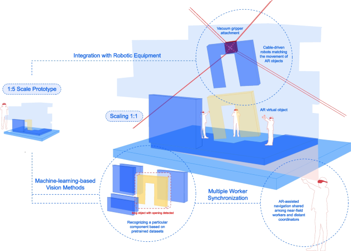
Strategic roadmap for scaling the AR workflow
9 Discussion and conclusion
The research presented an AR-driven framework to improve the production efficiency by providing workers with hands-free access to virtual content and information through interactive experiences. The developed immersive AR environment, deployed through a HoloLens HMD, includes user-friendly features such as an interactive assembly sequence guide and a module library. It employs continuous marker-based tracking and virtual snap-to-place features to simulate the virtual environment in the physical world. A case study of a CLT-based family house, situated in the urban village context of China, was used to demonstrate the potential applications of AR-assisted assembly. However, the developed AR environment remains highly adaptable to other building scenarios.
A 1:5 scaled prototype model was manufactured using flat, timber-based components and assembled through AR-assistance. The study concluded that there is significant potential for self-builders to construct with the guidance of AR technology, based on the constructability, operability, and user experience of the AR environment. The assembly logic and spatial instructions provided by the AR interface demonstrably aided in the production process. It was found that the assembly sequence of the prototype required adjustment in response to initial test observations, suggesting that adaptive sequencing is critical even in simplified conditions. These findings, however, are specific to the scaled prototype and do not fully account for the complexities of real construction environments.
We acknowledge the importance of establishing a conceptual framework for scaling the proposed AR method to 1:1 full-scale construction workflow to address this limitation. While the interaction design, marker-tracking logic, and spatial interface features are transferable primarily to full scale, additional considerations must be addressed. For example, full-size CLT elements pose occlusion challenges when workers operate near, and may require a hybrid workflow in which one or more users step back to coordinate the overall view while others handle localized assembly. This emphasizes the need for synchronized, multi-user AR environments in which shared virtual states are centrally managed and dynamically updated in real time. Future implementations will thus include centralized synchronization protocols, allowing multiple users to access and interact with a consistent, live assembly process model.
Furthermore, coordination with lifting equipment and site machinery introduces a new scale of interaction complexity. Full-scale deployment may benefit from AR cues for human operators and signaling machine-based operations, such as crane positioning or robotic gripper movement. Integrating these tools into the AR workflow through sensor feedback or digital twin interfaces can ensure a seamless handoff between human- and machine-led tasks. Real-scale experiments in prefabrication factory settings are proposed as the next step, offering controlled environments for validating equipment integration and collaborative task flows.
Regarding tracking robustness, scaling up will also require adopting machine-learning-enhanced computer vision methods to supplement or replace marker-based tracking in cluttered or partially occluded environments. The increased variability in lighting conditions, surface finishes, and human error at construction sites necessitates more adaptive visual understanding and predictive placement.
Although the primary focus of this study was a scaled prototype, the underlying insights are intended to guide future developments at a real scale. The logic of spatial guidance, task sequencing, and immersive feedback is conceptually scalable, particularly with advancing AR hardware capabilities and collaborative software infrastructure. This direction aligns with recent studies exploring AR in construction-scale workflows (e.g. Mitterberger et al., 2020; X. Yang et al., 2022), supporting our claim that the method can inform a new paradigm for mixed-reality construction support tools.
The design outcomes in this research extend human capabilities by offering an interdisciplinary approach to design-to-production through the use of AR. Such work holds significant implications for the technological advancement and digitization of the AECO industry, while contributing to more inclusive, adaptable, and efficient practices for self-building and high-density urban development.