Article Content
1 Introduction
RCM is a pneumatically driven, single-cylinder and single-stroke engine that is designed to simulate various engine operating conditions. It enables varying many parameters that affect efficiency of a combustion process (such as compression ratio, stroke length etc.). There is no rotary motion in a RCM and turbulence level is very low. Low vibration and optical access into the cylinder are its superiorities [1]. These devices are mainly utilized in combustion studies to gain insight into the auto-ignition phenomenon and chemistry [2]. Zhou et al. investigated auto-ignition characteristics of biodiesel and n-butanol mixtures in a RCM. They varied the volumetric amount of n-butanol and studied on its effects. They also measured ignition delay times of such mixtures at different pressures and equivalence ratios, and concluded that ignition delay time is inversely proportional to pressure and equivalence ratio, irrespective of the mixture content. Additionally, it was stated that n-butanol had a retarding effect on auto-ignition below a certain temperature value and over this, the retarding effect of n-butanol diminished as temperature increased [3]. Drost et al. measured ignition delay times of some DMEs (dimethyl ether) in a RCM. They varied temperature and pressure. Results of their study revealed that ignition delay times of tested DMEs were very close at higher pressures, while some discrepancies were observed at lower pressures [4]. Lee and Song investigated ignition delay times of hydrogenated n-butane mixtures by varying pressure, equivalence ratio and temperature. They evaluated effects of hydrogen on both ignition delay time and chemistry. Results of their study showed that ignition delay reduced with the increase in pressure and equivalence ratio. However, hydrogen addition increased ignition delay [5]. As one can see, equivalence ratio, pressure, temperature and fuel type are studied parameters in a RCM. With both numerical and experimental approaches, researchers have mainly focused on effects of these parameters on ignition delay time and chemistry. [6,7,8,9,10,11]. On the other hand, researcher also focused on knocking, auto-ignition and pre-ignition characteristics, and fuel injection strategy in a RCM [12,13,14,15,16,17].
In conditions such as low temperature and pressure, or when less flammable or lean fuel/air mixtures are used, any kind of ignition improvement is necessary. Turbulent jet ignition is an alternative ignition method in which a jet of post-combustion products is introduced into the combustion chamber. These products speeds up the ignition by igniting fuel/air mixtures at several spots. Trombley et al. numerically investigated turbulent jet ignition characteristics in a RCM and compared various ignition methods. The numerical study showed that F-24/air mixtures could be successfully ignited under low pressure and temperature conditions using turbulent jet ignition method [18]. Another alternative ignition method is hot surface ignition. In this method, a glow plug creates a surface with high temperature and this surface enables ignition. To analyze ignition and combustion characteristics of ammonia, Zhang et al. conducted experiments in a RCM using spark and glow plug ignition systems. It was reported that glow plug ignition enabled fuel/air mixture to be ignited at lower temperatures and lean mixture conditions in comparison with spark plug ignition. Additionally, it was also reported that flame propagation patterns depended on the type of the ignition source [19]. Adding highly flammable fuels into the fuels with low reactivity can improve ignition characteristics and can also be considered as an ignition enhancement method. In another study by Zhang et al., the ignition characteristics of various ammonia/methanol mixtures were investigated by measuring the ignition delay time in a RCM. Results showed that methanol improved OH radical formation and led to a decrease in ignition delay time [20].
Lasers are competitive substitutes for conventional spark plugs, with many advantages, including control of ignition location in the cylinder (yields optimization of combustion duration), the ability to simultaneously ignite fuel air mixture at multiple spots and the ability to deliver multiple laser pulses to the same spot [21]. So far, laser ignition has been extensively investigated by many researchers in various types of engines and combustors, and its positive impacts on combustion and emission characteristics have been elaborated. However, the literature barely lacks of laser ignition studies conducted on RCM. Dumitrache et al. studied on the laser ignition characteristics of CH4/air mixtures in a RCM at different equivalence ratios using a Nd:YAG laser ignitor. They mainly focused on lean flammability limit, minimum ignition and spark energies. They also evaluated flame formation and propagation characteristics using Schlieren imaging technique. Unlike the other studies in the literature, they specified a lower lean flammability limit with the utilization of the laser ignitor. However, minimum spark and ignition energies were in good agreement with the literature [22].
In this study, combustion and particulate emission characteristics of directly injected methane/air mixtures were investigated in a rapid compression machine (RCM). A passively Q-switched Nd:YAG laser ignitor with different number of ignition pulses (1, 2 and 3) and a constant pulse duration (a pulse energy of 9.2 mJ, pulse duration of 0.9 ns and wavelength of 1064 nm) was used to ignite the fuel/air mixture. All experiments were carried out with a fixed compression ratio of 13, 100 bar of injection pressure, and air–fuel equivalence ratio of 3.3. This study mainly focuses on the effects of number of ignition pulses on combustion and emission characteristics. The reliability of the results obtained was ensured by repeating each experiment at least 40 times at every test point.
2 RCM (Rapid compression machine) setup
Understanding the physical and chemical processes that occur in a combustion chamber is of great importance with respect to power output of the engine which is controlled by the transient processes. As previously stated, the ignition, combustion and emission characteristics of methane/air mixtures were investigated in a Rapid Compression Machine (RCM). RCM is a pneumatically driven single-cylinder engine designed to simulate a wide variety engine-like operating conditions. It enables adjusting various parameters that can affect the injection, ignition and combustion processes, pollutant formation and accordingly, power output of the engine. A RCM can perform one compression and one partial expansion stroke and allows compression ratio to be optionally chosen. In the RCM, there are two concentrically located pistons (inner-working piston, outer-driving piston) which move in reverse directions. This reversed motion provides mass balance and a non-vibrating atmosphere. RCM also provides optical access to the combustion chamber, and these features make the RCM suitable for optical diagnostic tools. Schematic of the RCM can be seen in Fig. 1 [23].
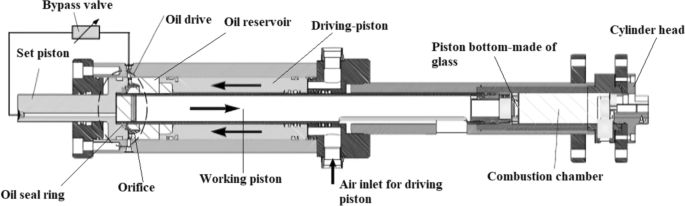
Schematic of the RCM
The RCM can be divided into two functional units, “experimental volume” and “driving unit”. The experimental unit consists of components related to compression chamber such as cylinder, piston, cylinder head etc. Demountable cylinder wall allows cleaning of the optical piston, other optical windows and the inner side of the cylinder. As the name implies, functions of “driving unit” include driving, mass balance, stroke, and motion arrangement. In addition, the” set piston” at the back end of the RCM is used to regulate the length of the stroke between 100 and 250 mm (Fig. 1) [23].
The working principle of the RCM is based on the reversed movement of two coupled pistons. Before initiating the compression stroke, components of the RCM must be in a pre-defined position as shown in Fig. 2 [23]. Through air inlets, a pressure up to 50 bar is applied to the outer piston, and the piston is then directed towards (throttle ring-4) the back end of the RCM. The connecting tube is located in the cylindrical sparing, and radial sealing ring (3) on the sparing prevents oil leakage into the sparing. The piston (connected to the tube via an O-ring) is at the bottom dead center and RCM is now prepared for compression stroke. To initiate compression stroke, a solenoid valve (2) opens and pressurized oil slowly flows from the outside into the cylindrical sparing (slow stage). The oil pressure causes connecting tube to be segregated from the sparing. Rapid compression stage starts when connecting tube passes radial sealing ring (3). A large amount of oil flows through sparing and piston moves to the top dead center (Fig. 3) [23].
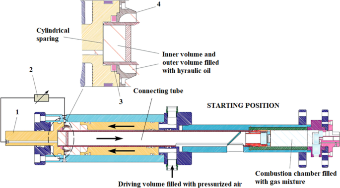
Position of RCM components before compression stroke [23]
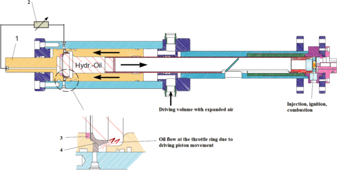
Position of RCM components after compression stroke [23]
Lastly, pressurized air is used to vent the gas in the combustion chamber and return the RCM to its starting setup. Stroke measurement is performed with an inductive encoder mounted on the connecting tube. The encoder must be reset before the compression stroke in order to compensate for perturbing effects such as increased temperature and pressure (ambient or resulting from operating) and thus to achieve high sensitivity [23].
The RCM used in this study is Testem TeRCM-K8401 (Fig. 4), which has high sensitivity and reproducibility. It can perform 30 shots per hour. It can operate with pressures up to 200 bar, and compression ratio can be selected between 5 and 25 (compression stroke between 50–240 mm). It also allows testing of various types of gases and gas mixtures and provides optical access from side, top and bottom of the cylinder.
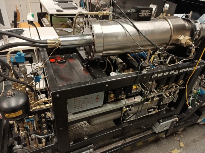
Rapid compression machine
The Schlieren setup utilized in this study is in Z-configuration. It is a mirror-based setup and comprises of two mirrors, a high-speed camera (Photron’s FASTCAM SA-X2 – with 12,500 fps recording rate), a parabolic mirror, an achromat, two filters, a white light source (Energetiq Technology EQ-99-FC) and a knife edge. The schematic of the Schlieren setup is given in Fig. 5.
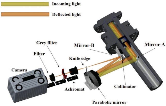
Schlieren setup (From the piston head window)
2.1 Other equipment in RCM setup
The polished cylinder head houses a laser ignitor, a pressure transducer and an injector. The characteristics of the injector are key factors in determining combustion and emission performance of an engine. Design parameters such as nozzle shape, size, number etc. also determine the power output and service life of the injector [24]. In this study, a seven-hole injector was used. It has a central nozzle hole and other six nozzles are circularly located around it. But, injection pattern is not symmetrical since two of the outer nozzle holes have steep angle.
To ignite a fuel/air mixture with a laser ignitor, the laser beam is directed into the combustion chamber with optical elements. Contaminants in the fuel/air mixture acts as an ignition source by supplying electrons that can absorb the energy of the photons. After a certain amount of energy is absorbed, such electrons interact with fuel molecules and ionize them. Subsequently, energy density of the fuel/air mixture increases and hence plasma, shockwave and ignition kernel are formed, respectively [25,26,27]. In respect to this, a laser ignition system equipped with a diode pumped-passively Q-switched laser ignitor, which has a laser energy of 9.2 mJ, pulse duration of 0.9 ns and wavelength of 1064 nm, was utilized. The examination of measured pressure profiles is of great importance in terms of qualifying the effectiveness of the combustion process. Therefore, a pressure transducer (Kistler 6061B) was used to measure in-cylinder pressure so that performance metrics such as indicated mean effective pressure, indicated work and efficiency could be calculated. Lastly, particle emissions were measured with a DMS 500 Fast Particulate Analyzer. This device measures particle size distributions, number and mass, and total concentration of the particles.
3 Experimental conditions in RCM experiments
All experiments were conducted under room conditions. Equivalence ratio (λ) was set as 3.3. As the boost pressure of the RCM (1.3 bar) was not changed, a fixed amount of air was ensured at each compression cycle. On the other hand, the correct amount of fuel calculated based on equivalence ratio was fed into the cylinder by optimizing injection duration. Compression ratio, and injection pressure were set as 13, and 100 bar, respectively. In the RCM that was used in this study, those parameters were set through RCM CAMAS software. These operating conditions were chosen so that auto-ignition does not occur. Some important experimental parameters are given in Table 1. Furthermore, laser energy was kept constant at the value of 9.2 mJ, yet the number of consecutive ignition pulses (1, 2 and 3) were varied and so-called multi-pulse ignition was studied.
4 Results and discussion
Inıtıally, a sensitivity analysis was performed to determine the experimental error. To do this, a compression stroke with injection was performed 60 times and displacement of piston movement was recorded. Results showed that experimental error was very low (Fig. 6).
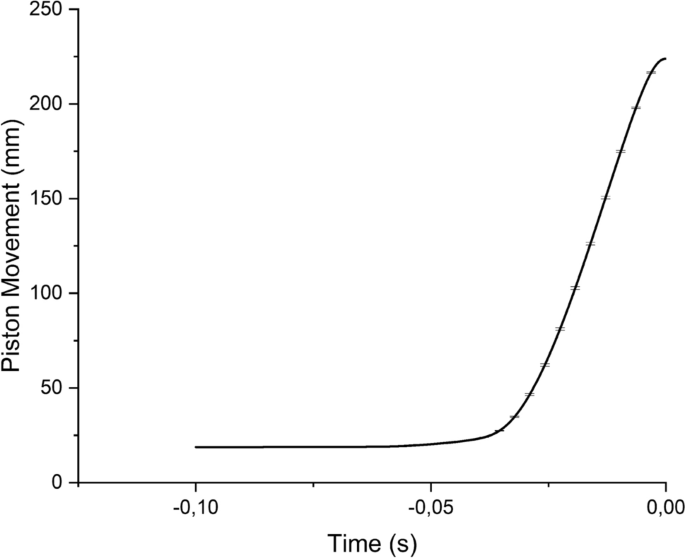
Experimental error analysis
As air/fuel equivalence ratio is 3.3, in other words, the fuel air mixture is very lean, the mixture either ignites or fails to ignite. Therefore, ignition possibility was determined in every test condition by calculating the percentage of successful ignitions in the total number of experiments. Ignition possibility was calculated as 72.72%, 88.09% and 92.10% at 1, 2 and 3 pulses, respectively. As seen, ignition possibility increases with number of pulses. In the laser ignition process, a laser beam is focused into the fuel/air mixture to initiate optical breakdown. If sufficient amount of energy is transferred into the plasma, a spark occurs in the focal point. Then, flame kernel develops and reactants are consumed [22]. The most important criterion in the laser ignition process is the ability of fuel molecules to absorb photon energy. Increased number of pulses rises this possibility. Moreover, along with the other laser parameters, the energy of the laser ignitor used in this study does not change with number of pulses. This fact also contributes to the increased ignition possibility.
As previously stated, each experiment was repeated at least 40 times to increase reliability of the results. Therefore, measured pressure values were averaged and averaged pressure values were plotted against time at each test point. Figure 7 represents mean pressure profiles at different number of pulses. Irrespective of the number of pulses, variation of the ignition is very low. In these profiles, the point where positive slope of the curve starts varying corresponds to the end of compression stroke. Then, ignition occurs and pressure value further increases (due to the heat release). The slope of the curve alters again and pressure value decreases because of the heat loses. The negative slope of the curve indicates heat transfer coefficient [22]. At the time of ignition, the size of the flame kernel is relatively small. Therefore, pressure rise (heat release) is not that distinct. Afterward, the slope of the pressure curve increases and it becomes steeper due to the rapid propagation of flame front (with larger surface area). In the RCM, mean effective pressure and efficiency may be relatively low due to the fact that turbulence level (slow burning rates) in the cylinder is weak [1].
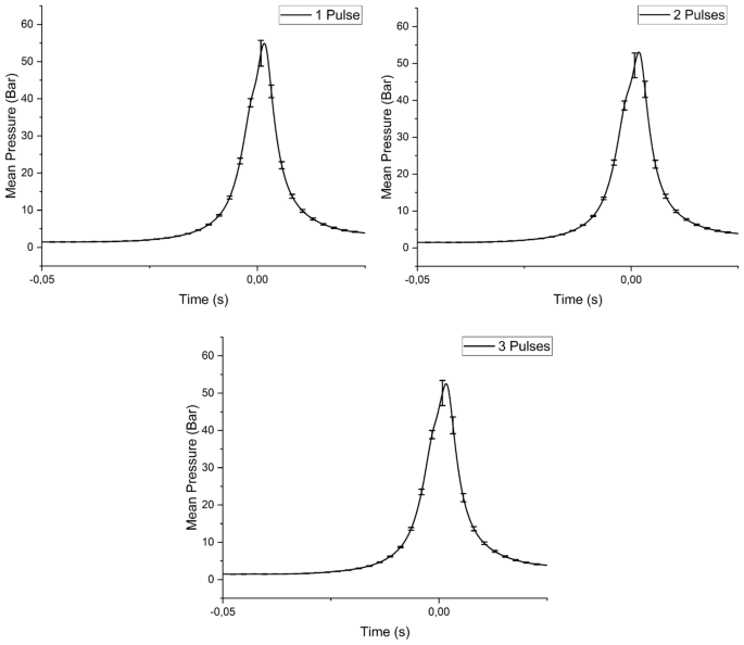
Mean pressure profiles at different number of pulses
Measured peak pressure values at 1, 2 and 3 pulses are 59.165, 59.985 and 59.387 bars, respectively. Unlike ignition possibility, effects of number of pulses on pressure distributions are not that significant and uniform. Mean peak pressure value and the rate of pressure rise are the highest at 1 pulse. At 2 pulses, rate of pressure rise decreases. However, mean peak pressure value is the lowest at these conditions. In conclusion, it can be said that number of pulses does not monotonously affect pressure profiles (Fig. 8).
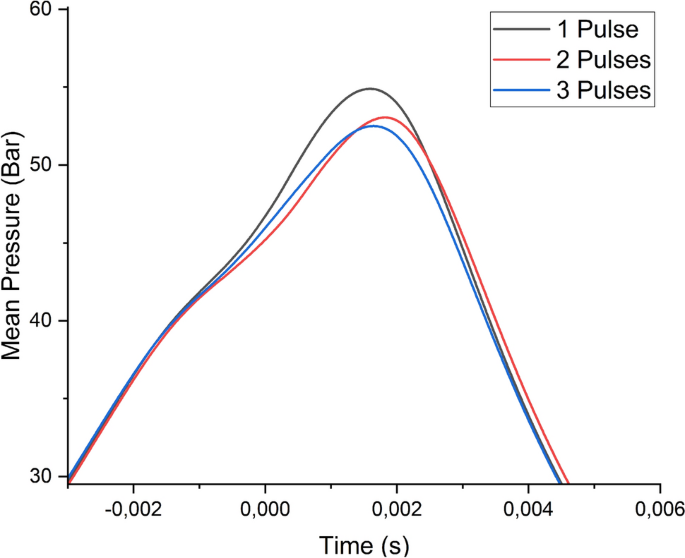
Pressure profiles at different number of pulses
Engine parameters such as indicated work, mean effective pressure and efficiency were calculated from measured pressure values using a MATLAB code, and results are given in Table 2. Similar to pressure profiles, number of pulses differently affects these parameters. Indicated work is directly related to piston movement during the expansion stroke. As seen, indicated work decreases as number of pulses increases. However, standard deviation and the difference between minimum and maximum indicated work values increase at 2 pulses, while a decrement is present at 3 pulses compared to 2 pulses. Indicated mean effective pressure is a performance parameter that specifies work capacity of an engine independent of the piston movement [28]. Indicated mean effective pressure values at 1 and 2 pulses are very close. However, it decreases at 3 pulses. Efficiency can be defined as the ratio of work to chemical energy of fuel. It represents a uniform dependence on number of pulses. It decreases as number of pulses increases. Lastly, calculated coefficient of variance values at 1, 2 and 3 pulses are 0.06611, 0.11189 and 0.10299, respectively.
Schlieren images are presented at different times; in the beginning of the experiment, at 26.32 ms (when flame becomes visible and begins to propagate), at 27.44 ms, and at the time when flame fully occupies cylinder volume. At the time of ignition, there is no density gradient in the cylinder. However, laser-ignited flame kernel rapidly transforms into a propagating flame, regardless of the number of pulses. Flame front moves in all directions and swiftly occupies cylinder volume (Fig. 9, 10 and 11). Independently from number of pulses, burning rate is high enough. Yet, it is the highest at 1 pulse. There is a relationship between burning rate, combustion duration, heat losses and efficiency. As burning rate increases, combustion duration shortens, heat losses decrease and efficiency increases. This complies with the efficiency values in Table 2.
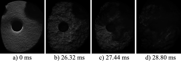
Schlieren images at 1 pulse
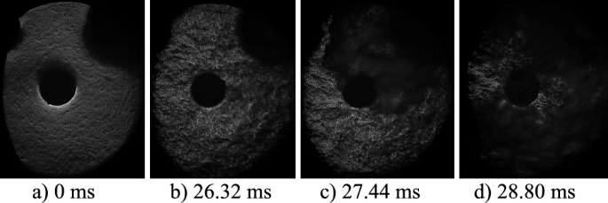
Schlieren images at 2 pulses
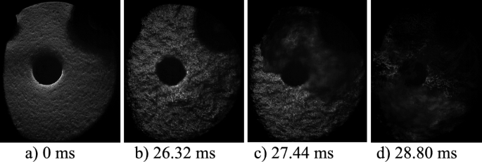
Schlieren images at 3 pulses
Flame luminosity images were processed using another MATLAB code. Flame surface areas at different pulses were calculated as a percentage of the luminosity image. In Fig. 12, flame luminosity images at 1 pulse are given with different time intervals. At the time of ignition, ignition spark can be clearly seen. Flame starts propagating right after 26.32 ms (Fig. 9), and ignition spark is delivered into the fuel/air mixture at 25.44 ms. The difference between these two values indicates (roughly) ignition delay time.
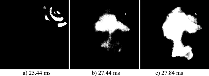
Flame luminosity images at 1 pulse
The non-uniform effects of number of pulses are present on flame luminosity. First increase in the burnt area is due to the ignition spark. Increasing number of pulses from 1 to 2 leads to an increase in flame luminosity and the highest luminosity occurs at 2 pulses. At 3 pulses, flame luminosity is even lower than that at 1 pulse (Fig. 13).
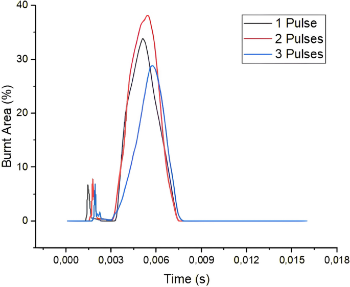
Burnt window areas at different number of pulses
In Figs. 14, 15 and 16, the normalized particle number size distributions are presented at 1, 2 and 3 pulses, respectively. In these figures; Dp is the particle diameter, dN is the number of particles in the range (total concentration) and the dlogDp is a value which depends on channel width of emission analyzer.
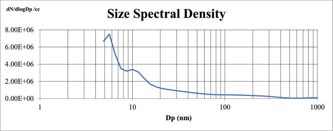
Normalized particle number size distribution at 1 pulse
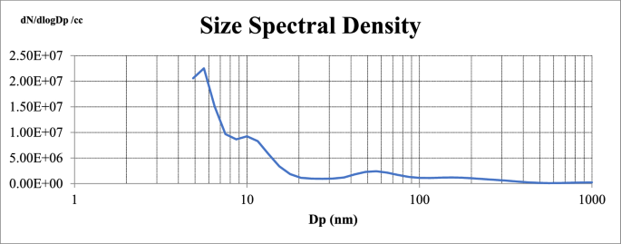
Normalized particle number size distribution at 2 pulses
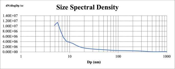
Normalized particle number size distribution at 3 pulses
Carbon atoms in fuel molecules lead to particle emissions. In this study, most of the emitted particles are small in size. At 1 and 2 pulses, emission profiles are similar in trend but particle emissions are higher at 2 pulses. At 3 pulses, particulate emissions slightly decrease but not lower than the values at 1 pulse. Irrespective of the number of pulses, emitted particles peak at a diameter of ~ 6 nm and then sharply decrease. This indicates that the most frequently measured particle diameter appears to be nearly the same for different number of pulses. However, emitted particles slightly increase at ~ 10 nm at 1 and 2 pulses. At 2 pulses, a 3rd increment pattern is also present. At 3 pulses, emission profile has an unimodal distribution. Similarly, number of pulses non-uniformly affects spectral emission distributions. As a conclusion, it can be said that the differences in emitted particles based on the number of pulses are both in the size distribution and in the quantity changes.
5 Conclusions
In this study, effects of number of consecutive laser ignition pulses on combustion and emissions characteristics of methane/air mixtures in a rapid compression machine were investigated. As number of pulses increased, ignition possibility increased. It was 72.72% at 1 pulse and became 92.10% at three pulses. Differently from ignition possibility, effects of number of pulses on pressure distributions were not that significant and uniform. Variation of ignition was low irrespective of the number of pulses. Calculated engine parameters such as indicated work, mean effective pressure and efficiency also represented a non-uniform dependence on number of pulses. Furthermore, the time when flame fully occupied the entire combustor volume increased as number of pulses increased. Lastly, it was found that the majority of the measured particle emissions were almost the same in diameter and number of the particle emissions was the highest at two pulses. These findings highlights the importance of ignition source and requires a thorough understanding of the processes that lead to formation of a spark through optical breakdown and optimization of the time interval between the pulses.
To be commercially competitive and practically usable, the size of a laser spark plug must be similar to that of a conventional spark plug to be able to be installed on the engine, and the production costs and therefore the selling price must also be comparable to that of a conventional spark plug. However, transmitting the laser beam into the combustion chamber with the desired properties depending on the application over a wide operating condition range, and the temperature and vibration resistance of the laser spark plug still remain major challenges [25]. These problems need to be resolved before laser spark plugs can be used as an alternative ignition source.