Article Content
Introduction
Following the advancements witnessed across various industrial domains, the fields of architecture and construction have undergone significant transformations in their design and production methodologies in recent decades [1, 2]. Amidst these changes, due to the progressive integration of digital technologies in these fields, computer-controlled Additive Manufacturing (AM) has emerged as a pivotal technology, showcasing immense potential in addressing the escalating demand for automation, customisation and optimisation.
Several extrusion based AM techniques and materials have been explored in recent years with application to the construction industry, such as Contour Crafting [3, 4] or 3D Concrete Printing (3DCP) [5]. Although concrete contour crafting shows promise for applications like low-income housing, emergency shelters, and complex luxury structures, widespread adoption remains unlikely, with anticipated low impact. Key challenges include efficiently scaling the process for large buildings [6], reinforcement [7] and circularity concerns [8]. Producing smaller components for transport and on-site assembly of larger systems such as walls or structural elements is a feasible approach that aligns with circular construction practices, such as Design for Disassembly [9, 10].
Yet, several challenges must be addressed for the practical application of 3DCP to the production of prefabricated systems amongst which are precision, surface quality issues, particularly in the system’s internal and external interfaces [11]. Furthermore, it is unlikely that a single material system can address the different functional and technical requirements which building elements must face. The current state of the technology often oversimplifies design, production, and products to fit within its capabilities, failing to adapt to the complexity of real construction sites and building processes [12].
In this study we focus on the application of 3DCP to building walls. 3DCP can be effectively used to produce blocks for this use-case with good durability, mechanical performance and impact resistance [13]. However, due to process and material properties, challenges remain in terms of user safety due to irregular hard edges of the wall surfaces finishes and poor sound absorption characteristics inherent to hardened cement materials. Hence, this study explores the sequential integration of two additive manufacturing processes—concrete and cellulose—to create a wall system composed of uniquely shaped, interlocking blocks. Functionally, the system consists of two layers: (1) a 3D-printed structural concrete panel serving as the exterior finish and facilitating the connection between components, and (2) a 3D-printed cellulose layer that provides the interior finish and acts as an acoustic insulator, optimized through formal design.
The interlocking features of the concrete blocks contribute to the structural integrity of the wall, making other chemical bonds between components unnecessary for structural purposes, and allow a more efficient and seamless construction process, reducing the labour required on the construction site. Conversely, the use of cellulose– a biopolymer with a sustainable matrix– in the inner face stems from its ability to improve sound absorption.
This study uses a research-by-design methodology [14] to develop and test a concept for an interlocking composite wall system. The research is developed in design, prototype and analysis cycles to optimize the properties of the basic wall unit, a composite 3D printed block, and the subdivision logic concerning the selected digital fabrication process.
This paper describes in detail the design-to-production workflow for a composite 3DCP blocks wall, and the 3D printed cellulose finish. In Sect. Background we discuss the benefits and drawbacks of applying 3DCP prefabrication in real construction contexts, as well as the combination of these processes with printed biomaterials. Then in Sect. Concrete Wall, the overall subdivision logic of the wall, the design for additive manufacturing of the 3DCP blocks and their robotic fabrication are described. In Sect. Cellulose Coating, we present the computational design logic for cellulose printing, including the shape optimization process, the production setup and the printing tests. In Sect. Geometrical Conformity, we compare the as-designed geometries of the wall with the results obtained through the proposed methods. Lastly, in Sect. Discussion and Conclusion we discuss the main results.
Background
Several large scale 3D printing onsite approaches have been described in the literature and adopted by several companies for the production of 3D printed walls [15, 16]. Researchers have focused on critical issues to enable the use of 3DCP for engineering, such as reinforcement [13, 17, 18], or architectural applications, such as surface finish [16, 19, 20]. However, crucial issues remain regarding the sustainability of site produced 3D printed walls [8, 21], wherein the technology automates the process of construction without considering the issues of its deconstruction, reuse, or recyclability [22].
The ability of this technology to create complex and customised structures can be leveraged to design components that are easily, assembleable, separable and reusable [11]. This flexibility in design allows for the creation of interlocking or modular elements that can be assembled and disassembled without damaging the individual parts. Recent literature on masonry systems demonstrates that dry staked interlocking block walls are up to 120% faster to build and thin-jointed and mortar-bedded interlocking-block masonry walls are 60–90% faster than conventional flush blocks [23]. Other studies demonstrate advantages compared to traditional masonry in cost, reduced labor skill, decrease risk of moisture damage and shrinkage, more stability during construction, immediate loading capacity and the possibility to build in all weather conditions [24].
By removing the need for mortar to connect the blocks, an environmental advantage is also achieved: the elimination of binding agents facilitates disassembly, enables reusability of components, and reduces material waste at the end of a structure’s life cycle [25]. Furthermore, this approach aligns with circular economy principles by allowing components to be reused in future constructions, thereby minimizing the demand for new raw materials and reducing the overall carbon footprint of building projects.
Conversely, documented disadvantages of dry staked interlocking block walls are related to the requirement for higher standard of base flatness, to ensure level, and block manufacturing precision [24]. Recent studies have demonstrated that uneven block interfaces and variations in block height reduce contact area between layers and can lead to uneven load distribution [26].
The precision of 3DCP enables the incorporation of connection points or interfaces specifically designed for assembly and disassembly. By combining this approach with compression dominant structures it is possible to produce prefabricated and disassemblable systems [27]. In the Tor Alva project, Anton et al. [9] investigate several strategies to ensure parts interlock with precision, such as integrating casted concrete parts and printing parts over sacrificial layers of the previous component. Integrating casted parts is unwieldy in the production of 3D printed blocks, as the interfaces surround the blocks in all directions. Also, while printing over previous layers ensures a tight fit, this approach is not easily adaptable to more complex interlocking between multiple parts and increases production waste.
Several researchers have investigated the use of 3D printing of different materials as a formwork for concrete blocks. Xu et al. [28] explores 3D clay printing as formwork for customized concrete blocks with integrated plant support and irrigation system. Emami [29] investigates using 3D printed elastic resin formwork for casting interlocking concrete blocks, exploring the challenges and potential for mass customisation. In both instances, the blocks are massive and produced in a two-step process, failing to leverage the possible weight and material reductions that could be attained through 3D printing.
The use of cellulose as 3D printing material for producing partition systems has been explored by Ramsgaard Thomsen et al. [30], who proposes a 3D printed wall system with variable blocks with interlocking features. Cellulose 3D printing has also been explored by Agha & Knaack [31] for acoustic and shading panels. Yet, both approaches have limitations related with the material properties for use as an external wall system. To our knowledge the combined use of 3D printed cellulose and concrete has not been explored. The combined use these techniques can potentially produce effective solutions that address issues of automation and circularity.
Concrete wall
The design of the concrete wall seeks to address the following goals: (1) achieve a high level of reversibility of the wall, (2) ensure that it is self-supporting, (3) explore the 3DCP process as a design feature, (4) provide cavities for services. The previous goals will involve trade-offs, for instance improving reversibility implies favouring mechanical connections in detriment of strong chemical ones and reducing the weight of the components [32], which can have impact on the strength of the structures.
Thus, the design of the concrete wall follows the ensuing design principles: (1) it consists of a double-wall system of prefabricated masonry; (2) stability is mainly ensured by incorporating an interlocking system, which misaligns the horizontal and vertical joints between the inner and outer wall panels, complemented by weak chemical connections for waterproofing; (3) it provides the external surface finish; (4) it supports the application of cellulose printing on the inner face; and finally, (5) it is designed so that the blocks are lightweight and easily transportable, allowing for assembly and disassembly by a single operator.
Design
Several design-to-production cycles were conducted to finetune the base block design parameters. Preliminary experiments were conducted to evaluate various nozzle diameters and manufacturing parameters with the goal of enhancing printing accuracy and reducing block weight. As detailed in the Sect. 3.3 Fabrication, the optimal configuration was achieved by reducing the layer height to 7.5 mm and the layer width to 30 mm, resulting in significantly enhanced manufacturing accuracy and lighter elements.
The basic unit of the wall is a double block, an internal and an external panel separated by a 10 mm void, vertically and horizontally shifted, and connected with a thin bridge to limit thermal bridging to a minimum (Fig. 1). The shift creates a vertical interlocking with the upper and under rows, and a horizontal interlocking laterally. All block measurements, with the exception of layer width and height, are parametrically customizable, however, the dimensions of the block type 2B were set to 350 mm in length and 200 mm in height to keep the average block weight under 20 kg. The thickness of the interior block is set to 100 mm, its interior face is flat to receive the cellulose coating. Conversely, the outer wall face has a variable width depending on the desired exterior finish.
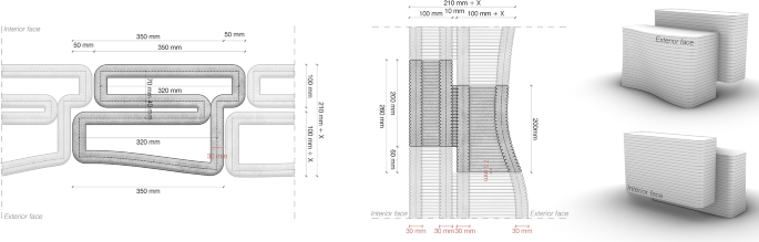
Section of a type 2B block
The wall design was oriented towards 3DCP production. This means that all measurements had to integrate the predicted layer width into the printing process. The horizontal overlap distance of the blocks in the interlocking system was determined based on an analysis of the rounded corners in the printed geometries. Considering an average rounding of 25 mm, a minimum overlap distance of 50 mm was set. Additionally, the vertical overlap distance must be adjusted in multiples of the layer height. Considering a layer height of 7.5 mm, 8 layers (60 mm) were determined as adequate interlocking.
To enhance the structure’s impact resistance by connecting the maximum number of blocks, a running bond masonry system was adopted, where the upper block interlocks between the two lower blocks. The combination of these design decisions results in 9 block types to produce a simple straight wall (Fig. 2).
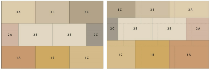
Wall subdivision strategy– (left) exterior view and (right) interior view with 9 block types
The assembly/disassembly sequence of the wall is row-wise unidirectional as consequence of the interlocking approach. The computational design strategy is aimed at the generation of custom-fit walls from the subdivision of a base surface, yet the dimensions of the 1 A, 1B, 2 A, and 2B block types are envisioned to be standard. Thus, the adaptation to the site dimensions follows a modular linear subdivision [33] in vertical and horizontal wall directions. Hence, the last row blocks (3 A, 3B and 3 C types) have custom heights, and the last column blocks (1 C, 2 C, 3 C types) have custom widths. This approach maximizes the reusability of the blocks by limiting the dimensional customization to the areas where it is required.
The developed prototype includes a proposal for an exterior surface geometric customization following a wavy surface. The computational code allows for customization of this surface, and a series of solutions with varying inclinations were tested, which will be discussed next. This approach leverages the capacity of 3DCP manufacturing for producing custom textures and complex shapes, yet this does not favour the wall’s reversibility in other contexts, as the relative positions of the blocks become fixed. Nevertheless, the reuse of the blocks is still possible and the 3DCP process may be leveraged to produce custom-fit extensions.
Design for manufacturing
The production of any component through 3D printing requires a pre-production phase in which the shape to be produced is divided into a set of extrusion paths organized into layers. Figure 1, in the Sect. Design, illustrates the geometry of a 2B block, projecting its final geometry and the dimensions of the extrusion path (dashed line in the centre of the layer). Figure 3 illustrates the wall prototype design process in 5 phases: (1) wall subdivision; (2) integration of print settings; (3) cut-out of the wavy surface; (4) slicing; (5) simulation of design.
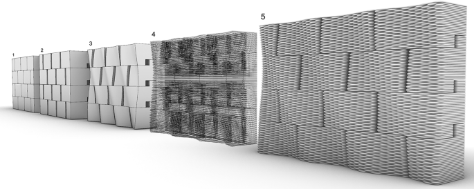
Steps from design-to-production of the concrete wall
The first two steps concern (1) the wall subdivision, described in Design, and (2) the introduction of a spacing between blocks to accommodate the expected layer width.
Step three allows the design of a corrugated surface without the use of support materials. Weber– Saint Gobain (mortar manufacturer) recommends a maximum unsupported overhang of 83º for the type of geometries we propose. However, our preliminary experiments indicate that the maximum inclination is dependent on rheological properties of the material during printing, but is also intrinsically linked to the geometry to be printed. In this case, knowing that the wavy surface of the block wall would only be 350 mm long, supported evenly on both sides, maximum inclinations of 126º, 114º and 100º were tested. The prototyping of each of the solutions revealed that only the typology with the lowest inclination did not show signs of elastic buckling during printing, it was therefore applied to the entire wall.
After defining the wavy surface, in the fourth stage, the block geometries were finally sliced, considering the previously defined layer height (7.5 mm). As the printing system does not allow extrusion to be interrupted between layers, the generated contours were joined together creating a single extrusion path. The parametric code allows the selection of the layer transition point, which can be adjusted for each part.
During this phase, it is possible to customize each extrusion path individually by adjusting its generation parameters to introduce a zig-zag in the printing path. In our experience, an alternating zig-zag printing path has positive effects on buildability by reducing the slenderness of the 3D printed walls and creating local bracing between layers. The relation between wall slenderness and elastic buckling in 3DCP is well established [34, 35]. These studies also propose that wall imperfections contribute to elastic buckling. In our experience, the bracing effect of alternating zig-zag paths reduces the risk of wall imperfections leading to failure. This customization, in addition to aesthetic goals, is also reported to improve adhesion between subsequent layers [36]. In our prototypes we introduced the alternating zig-zag path to improve the stability of the exterior block wavy wall in the fresh state. Step five predicts the final geometry of the blocks.
Fabrication
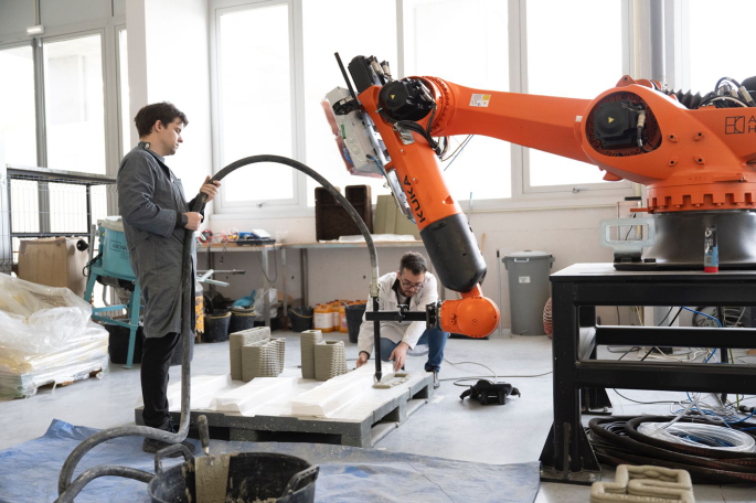
The prototypes of the wall were produced with our 3DCP setup which consists of three interrelated phases (Fig. 4): (1) production of the mixture; (2) pumping the material to the extrusion nozzle; and (3) layering of the material, with continuous filaments, following a specific print path. The first two phases were carried out using a MAI®MULTIMIX-3D mortar mixing pump — a custom 3D Concrete Printing setup comprising a continuous mixer and a mortar pump. Our previous experiments with non-integrated mixing and pumping systems revealed greater difficulty in ensuring consistent print sections during long print sessions [37]. The third phase was handled by an industrial robotic arm– a Kuka KR120 2700, which manipulated a fixed tubular tool attached to its flange.
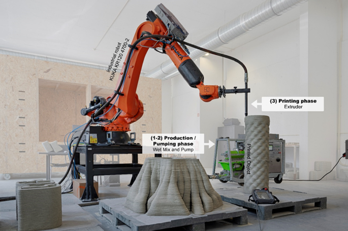
3DCP Robotic fabrication setup
The attached tool is a direct extruder which only allows 1 K printing. In this setup, only one material (or “component”) is used in the printer, typically a premixed mortar or concrete that requires minimal on-site mixing and no additional chemical activators. Hence, the Weber 160–1 dry mix for 3DCP processes was used to produce the wall prototypes. After adding the dry mixture, the water flow rate in the wet mixing chamber was adjusted to 265 L/h and the pump rotational speed was set to 15 Hz. This correlates to a measured extrusion flow rate of 74,4 L/h.
Custom printing setup for interlocking feature production
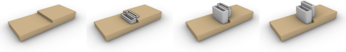
To produce the base interlocking features of the block, a custom printing setup was devised comprised of bases on two levels on which to print the blocks (Fig. 5). The bases can be cut from a single EPS block using hotwire cutting. For prototyping we used a larger plastic pallet as the first level of the base, on top of which EPS hotwire cut blocks are placed with the precise height of the interlocking feature. Since the height difference is constant between different blocks the EPS formwork is reusable for multiple production runs.
A series of preliminary tests were conducted to determine optimal printing parameters while maintaining a standard print speed of 100 mm/s. Initially, based on parameters optimized in prior experiments, a 20 mm extrusion nozzle and a 10 mm layer height were used, adjusting the material flow rate to achieve a layer width of approximately 40 mm. However, this setup resulted in excessively heavy blocks (around 35 kg each), which could hinder the assembly process. Furthermore, the low print resolution led to increased deviation of the printed geometry from the target geometry. Deformations arising from the process, including excessive settling of lower layers and pronounced rounding of block corners, resulted in noticeable discontinuities in geometric continuity between components, particularly evident on the wavy exterior surface.
3DCP Block robotic production
Ultimately, reducing the nozzle to 15 mm with a 7.5 mm layer height and stabilizing the extrusion flow to achieve a layer width of 30 mm improved geometric conformity between juxtaposed blocks while also reducing the average component weight to 20 kg. Figure 6 illustrates the series production of the wall blocks.
Immediately after printing, while the material was still fresh, the individual numbering of each block was stamped in bas-relief, facilitating the subsequent assembly process. Figure 7 shows the finished concrete wall.
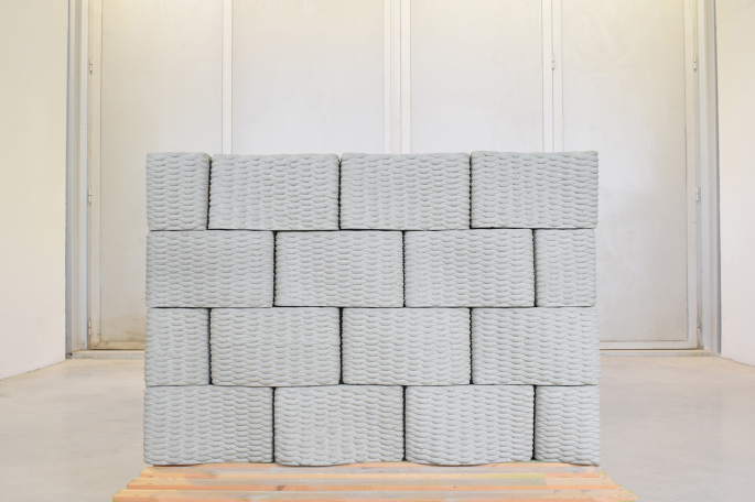
Assembled concrete block wall prototype
Cellulose coating
The cellulose coating layer serves as an internal finish for 3DCP blocks, addressing specific concerns related to interior wall finishing. These concerns include the presence of sharp edges, impact performance, and acoustic properties. While 3DCP blocks excel in impact resistance, they pose challenges in terms of user safety due to irregular hard edges and poor sound absorption characteristics inherent to hardened cement materials.
The application of 3D printed cellulose over 3DCP blocks offers a promising solution to these issues while also providing an opportunity to explore innovative design patterns that combine aesthetic appeal with functional performance. These patterns must combine good printability performance while also providing a large internal surface area to improve sound absorption. On the other hand, since the cellulose layer must be 3D printed over the concrete substrate, the blocks subdivision pattern becomes an inevitable constraint over the possible patterns. Furthermore, the bidirectional interlocking pattern creates a shifted running bond on the interior face which due to the exceptional nature of the edge blocks produces layers with uneven heights.
Design
To overcome these challenges a unicursal labyrinth pattern is explored. To generate this pattern an iterative graph algorithm based on the bond flip move proposed by Mansfield [38] was developed. The algorithm initiates by generating a zig-zag hamiltonian path starting on specific corner and ending on one of the remaining corners (Fig. 8A). Then it iteratively operates a random bond flip move on the chain n number of times (Fig. 8B, C, D and E). The bond flip move is implemented as a two-step process. First, two neighbouring parallel edges are randomly selected and rotated. This move creates two separate paths, one of which is a loop. Second, the two paths are reconnected by operating a bond flip move bridging both paths, by selecting a random edge of the looping path with a parallel edge neighbour not in the looping path.
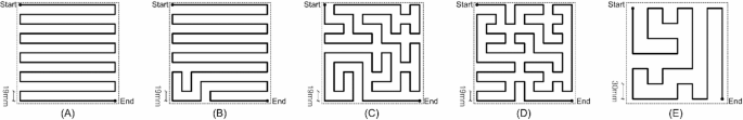
Pattern variations with variable randomization iterations: A) no iterations, B) 2 iterations C) and D) 50 iterations E) 50 iterations with reduced UV subdivision
The pattern presents interesting properties regarding the proposed application: the printing path is continuous, which is optimal in terms of printing time, the pattern is randomized but not repeating and has several linear features which de-emphasize the running bond of the 3DCP blocks. The randomization across blocks is possible, which avoids the creation of larger patterns that would expose the shifted running bond.
The hamiltonian path algorithm was integrated in a larger algorithm, aiming to generate paths for 3D printing, which exposes the following parameters: (1) area to fill; (2) pattern start and end points; (3) inter-filament axial distance; (4) number of randomization interactions; (5) number of layers; (6) a random seed value. Figure 8 presents some pattern variations where the first two parameters remained constant. Example A represents the base pattern with a distance between filaments of 19 mm, without any interaction. Example B adds 2 interactions and example C 50 interactions. Configuration D is like the previous one, but the seed value is randomized. Finally, example E changes the distance between the filaments keeping all remaining values the same as before.
Two slightly different implementations of the above algorithm were explored regarding their acoustic performance: (A) layers with different randomization levels (Fig. 9); e (B) all layers with the same level of randomization (Fig. 10). In solution A, all parameters are constant except the number of randomization steps per layer. This variation across layers creates small bridges at different levels from the top surface of the panel to the bottom. Conversely, in B, a single pattern is repeated across all layers.
In both cases, since the start and end points of each layer coincide, we reverse the printing direction in alternating layers to optimize printing time and reduce the drying deformation [39].
While it is possible that increasing the print resolution, such as by using a finer extrusion nozzle and smaller layer heights, could potentially improve the acoustic performance of the printed panels, a 6 mm nozzle and a 2 mm layer height were chosen to expedite the printing process and enhance the final strength of the printed geometries. Similarly, the number of layers was limited to a maximum of 12.
Additionally, our preliminary printing studies indicated improved cellulose adhesion on 3DCP surfaces when a levelling bed was printed beforehand. Therefore, using the same algorithm supplementary layers were created to improve cellulose adhesion across the entire surface of the block. The levelling bed consists of one or two cross-layered paths of parallel horizontal extrusions spaced approximately 5 mm apart.
Finally, the G-code, read by the 3D printing machine, was generated directly in Grasshopper after the acoustic optimization process described below.
Acoustic absorption optimization
To simulate the acoustic behaviour of the panels, the Pachyderm Acoustic Simulation plug-in for Rhinoceros 3D/Grasshopper was used [40]. This plugin consists of a suite of acoustics algorithms designed to predict sound behaviour and visualize sound propagation. To reduce computation time, the study was confined to a cubic space measuring two meters per side. On one face of the cube, the acoustic panels were arranged according to the aggregation principle established for the wall, with the sound emission point positioned at the centre of the space. From this emission point, as a representation of sound waves, 8312 vectors were projected toward the panels under analysis. Using Pachyderm, the reflections of the sound rays hitting the panels were calculated, with the assumption that sound propagation would be nullified after the fifth reflection.
The Evolutionary Solver in Galapagos for Grasshopper [41] was employed for the simulation/optimization process, as it was expected that the solution would converge to a global minimum. The objective function was defined as the minimization of the number of rays reflected by the printed surface on the first sound reflection. An optimization runtime limit of 40 h was set.
A preliminary experiment was conducted to determine more favourable geometric properties of 3D printed reticulated structures to absorb sound. A quadrangular mesh with variable parameters such as number of layers and inter-filament distance was used. The results showed that solutions with less layers performed worse, reprojecting vectors faster than solutions with 11 to 12 layers. Denser meshes, with smaller inter-filament distances, also performed worse compared to larger distances (20–30 mm).
Two more simulations were performed on the patterns described in the previous section, first testing Solution A (varying paths across all layers) and then Solution B (uniform paths across all layers). Optimized parameters during the simulations included filament spacing, the number of layers, and the number of iterations (Figs. 9 and 10).
The optimization of Solution A revealed an unexpected result. Although it was initially hypothesized that increasing the internal voids between layers– created by introducing small bridges– could improve acoustic performance due to greater geometric complexity of the voids, the simulation results suggest otherwise. The best performance was obtained with 0 iterations– all layers with the same path − 12 layers and a filament spacing of 17 mm, achieving 4,039 re-projected rays (Fig. 9). A possible explanation of this result is that the surface area perpendicular to the sound source– the surface of the printed filaments– is increased while the overall depth of exposed voids is decreased. Since if all layers are different most of the vectors are immediately re-projected before entering the pattern voids (spaces between filaments).
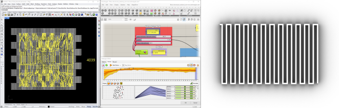
Solution A optimal result with 4039 reflected rays
In this context, Solution B, with uniformity across layers, naturally provided an improved response. The image below illustrates the best simulation result, with 3,906 re-projected rays (fitness), achieved using a filament spacing of 17 mm, 12 layers, and 75 iterations (Fig. 10).
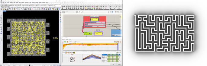
Solution B optimal result with 3906 reflected rays
Given that Solution A presents distinct challenges during the production phase, one of the results from the simulation was also produced. The selected result of Solution A to prototype yielded a fitness value of 4,799, with a filament spacing of 17 mm, 12 layers, and 30 iterations per layer. A sample from each solution was then adapted to the dimensions of the concrete blocks and subsequently printed.
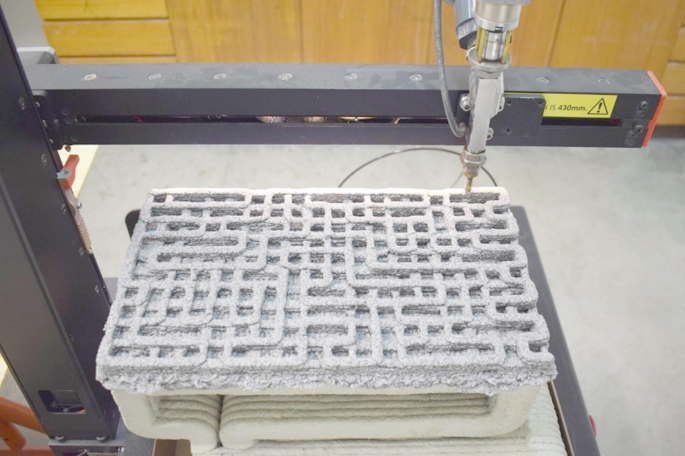
Fabrication
The cellulose printing process employed a LUTUM 3D printer (Fig. 11), a cartesian kinematics 3D printer developed by Vormvrij [42], primarily used for ceramic paste extrusion. Material deposition is controlled by the precise relationship between the rotation speed of a helical-ribbed screw and the air pressure applied to the cartridge, while three servomotors manage the extruder head’s movement according to the defined X, Y, and Z coordinates.
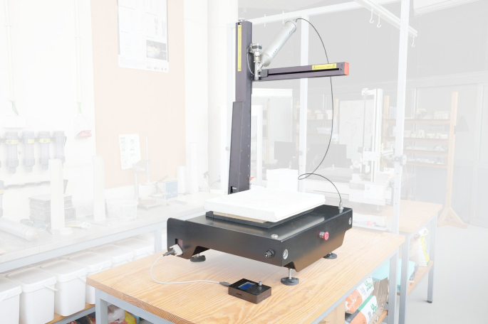
Cellulose printing setup with 3-axis LUTUM 3D printer
The preparation of the mixture starts by combining 10% corn starch (w/v) (VRW, Radnor, PA) with 76% water (v/v). After homogenising the materials, they are heated with vigorous stirring until a highly viscous hydrogel is formed. When the temperature of the hydrogel has dropped, 14% micronized cellulose (w/v) in small amounts is gradually added until a completely homogeneous mixture is formed. A small percentage of expanded insulation cork board dust was added to improve the drying behaviour. In the end, an extremely fibrous mixture is obtained, which can be extruded in greyish filaments using a helical screw rotation speed of 14 mm/s and an air pressure of 4.5 bar.
Printing the acoustic panels directly onto the pre-printed concrete blocks presented a series of challenges. The orientation of cellulose printing is inverse to the 3DCP printing position, making it necessary to rotate the concrete blocks and develop strategies to maintain their stability and levelness throughout the printing process. Given that each block’s exterior surface is uniquely undulated, a box filled with fine sand was used to support the pieces during printing. This method proved highly consistent, preventing any displacement of the pieces even under the operational vibrations of the equipment.
As the 3DCP surfaces used as a base are stratified and naturally contain minor geometric variations between layers, the printing of a levelling bed was tested. As validation, Fig. 12 shows three small square prototypes (10 × 10 cm) for each of the geometric solutions under study: (1) without an adhesion base; (2) with one base layer; and (3) with two crossed base layers. These tests were printed on a concrete block using acetate to prevent adhesion.
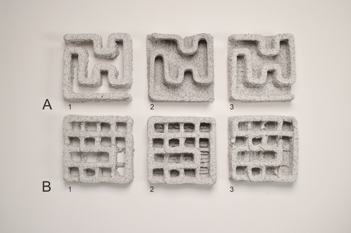
Prototypes of the two selected patterns (Solution A and B). Left column: no adhesion base; Middle column: adhesion base with one layer; Right column; adhesion base with two crossed layers
After manually levelling the concrete surface to ensure adequate clearance and avoid collisions, maximum deviations of approximately 4 mm were detected (gap between the extrusion nozzle and the concrete block in the worst section). To fill this gap, test results indicated better coverage using two base layers, effectively reducing voids between parallel extrusion paths. Conversely, in areas with reduced spacing, an excess of deposition was observed. Given the need to fill the rounded corners of the concrete surfaces to ensure proper alignment of the printed panels, a manual application of a cellulose levelling layer with a spatula was used. On top of this initial layer, the acoustic panels were printed with only one printed levelling layer. Figure 13 illustrates the printing of a panel with solution A.
Printing of Solution A panel prototype
Immediately after printing, excess material from the initial layers was removed, and the block was placed in a laboratory oven at 55 °C for 24 h.
Each design presented distinct challenges. On the one hand, Solution A, with a more complex structure, forms a three-dimensional mesh with multiple directional changes, where some layers are printed without the support of underlying layers. This results in small bridges that the cellulose filament must overcome. To address the material’s limitations in these cases and to prevent filament breakage, the printing speed was reduced from 10 mm/s to 5 mm/s, yielding better results. On the other hand, for Solution B, which has a zig-zag pattern, careful attention was required to manage the frequent directional shifts. The same reduction in speed was applied. However, after printing, particularly in straight regions at the edges, acrylic supports were added to prevent deformation of the geometries during the drying phase.
Figure 14 illustrates two printed blocks: on the left, Solution A—using varied paths across layers—and on the right, Solution B—with identical paths in all layers. Figure 15 illustrates the same part of the wall simulating the application of panel solution B.
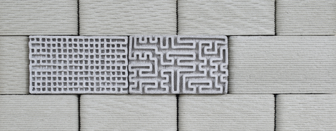
Panel prototypes on the assembled 3DCP block wall. Left: Solution A panel; Right: solution B panel
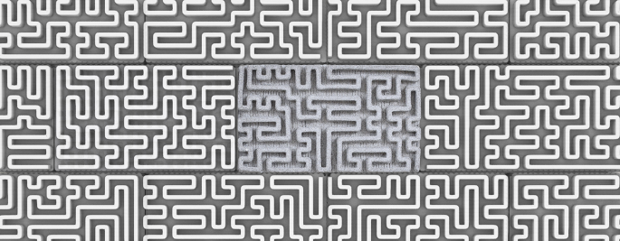
Simulation of the wall section with Solution B panel
Geometrical conformity
In this section we analyse the geometrical conformity of the produced blocks and the assembled wall with the as-designed block and wall geometry. The fully assembled wall and one of the blocks from the middle of the wall (block 10) were surveyed using photogrammetry to determine their accuracy vis-à-vis the as-designed wall and block geometries. The survey of the wall required 142 photos taken in a cylindrical pattern with a Nikon ZF6II camera. To obtain a full model of the block without two surveying setups, the block was hung, and the photos were taken in a spherical pattern at six different levels. 134 photos were taken with a Nikon D700 camera equipped with a Zeiss ZF.2 50 mm macro lens.
Both photo sets were aligned with Meshroom [43] to obtain a dense cloud and mesh. The models were scaled using ground control reference objects positioned in the surveying setup. The assembled wall and block point-cloud were oriented with the XY plane by minimizing the distance of the floor surrounding the wall and the underside of the block, respectively. The as-designed reference mesh of the wall was manually aligned in XY plane to the top layer of the 3DCP wall. The cloud of the block was aligned with the as-designed mesh using the Iterative Closest Point algorithm, constrained to rotations in the Z-axis and translations in the XY plane, with 50% overlap. The pair was aligned with final RMS of 1,01555 on 49,999 points.
Both the assembled wall and the block are compared with their as-designed dimensions. Figure 16 shows cloud-to-mesh signed distances for the assembled wall. We distinguish interface deviations, relating to the boundary of the wall that would be restrained by other building systems, and face deviations, relating to the surfaces of the wall defining spaces. Interface deviations are the most critical regarding dimensional accuracy while face deviations are important for stability issues. Figure 16 shows that interface deviations for the assembled wall are in the range of -5 to -10 mm for lateral edges and Vertical deviations for the top edge are in the range of -16.5 to -10.1 mm (first quartile and third quartile). The difference in size is accountable by a combination of factors. Vertical dimensional variation is caused by irregularities of the top layers and drying shrinkage. According to the dry mix manufacturer, drying shrinkage is expected to be in the range of < 1%.
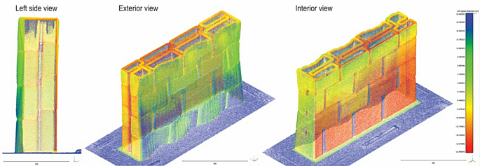
Deviations from as-designed geometry of the wall. Left: Left side view; Middle: Exterior axonometric view; Right: Interior axonometric view
Regarding face deviations, Fig. 16 shows that the wall is tilted towards the interior by 18 mm over the height of 845 mm. The tilt is visible on both sides of the wall, consequently, is likely to be a result of the accrue of deviations in the blocks.
The geometrical conformity analysis of block 10 reveals that side interfaces are close to the expected values, with deviations falling in the range of -3 to 1.5 mm (Fig. 17). These deviations imply that the as-designed block-to-block tolerance of 5 mm is slightly above the 3DCP process layer variability. This difference can account for the deviations that were observed in the side interfaces of the wall. Regarding the top and bottom interfaces of the block, the deviations are significantly larger. The interior block bottom interface has a high level of flatness, which is expected, in the range of -8.1 to -7.3 mm, but is significantly off the as-designed geometry. The top faces also show larger deviations than the side faces with − 5.6 to -1.9 mm for the interior block top face, and − 8.5 to -5.7 mm for the exterior block top face. These differences likely account for the wall tilt towards the inside, as there is nearly 5 mm difference between the interior and exterior.
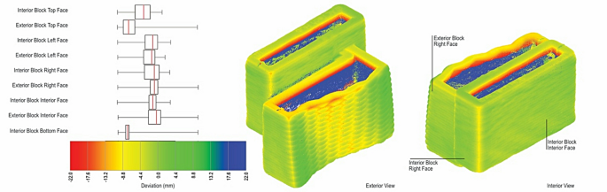
Deviations from as-designed geometry for all interfaces of a block
There is also a notable deformation of the wavy surface exterior face of the block wall. The deformation of the surface in outward leaning areas is negative while the opposite happens in inward leaning areas. This effect can be explained by the incremental plastic deformation that occurs while the nozzle presses the previous layers off-axis.
Regarding the cellulose patterns, a geometric conformity study was conducted to compare the target pattern with the produced pattern after fabrication. This comparison was based on photographic surveys of each printed prototype, revealing varying behaviours.
For pattern A, shown in Fig. 18, deviations of up to 3 mm were detected at certain directional changes (yellow circles in Fig. 18). This issue is more evident in areas with less support from lower layers (bridges). Due to this constraint, the printed filaments in these areas are not adequately pressed onto the lower layers, showing a thickness of less than 6 mm (red circles in Fig. 18). This difference was accentuated by material dehydration during the drying process. Nonetheless, reducing the print speed helped decrease material cracking, ensuring positive mechanical performance and reasonable alignment with the digital design.
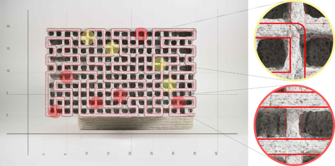
Geometrical conformity analysis from Solution A of the 3D printed cellulose panel. Yellow: Detail of a corner of the path; Red: Detail of the bridges
Analysing pattern B, a more constant material response was detected due to layer overlap compared to the previous example. However, as illustrated in Fig. 19, deformations of up to 3 mm were also observed in the corners due to the change in printing direction (yellow circles in Fig. 19). In this case, the absence of a mesh exacerbates this factor, leading to greater geometric deformations, which increase progressively layer by layer. Furthermore, in the larger segments, deviations occur due to the lack of support (sagging) of the printing walls during printing and drying phases (orange circles in Fig. 19). This issue was partially mitigated at the block outer edges by placing supports, as previously described, thus posing no issue for the final assembly of the pieces.
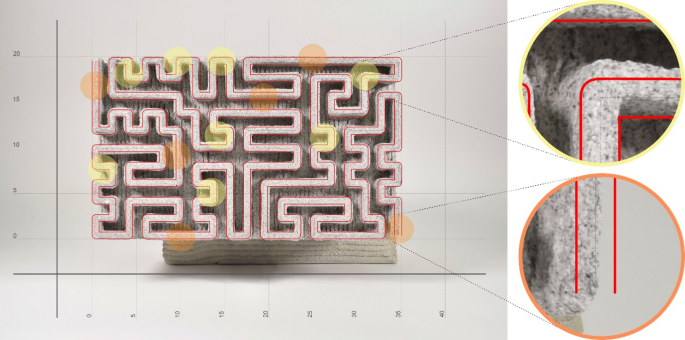
Geometrical conformity analysis from Solution B of the 3D printed cellulose panel. Yellow: Detail of a corner of the path; Orange: Detail of a long segment without support
Regarding material shrinkage, both previous images confirm that the length and width of the blocks were maintained (350 mm x 200 mm), with zero shrinkage and a high correspondence to the digital model. Conversely, for panel height, a shrinkage of approximately 21% was observed. The digital model, designed with 12 layers, aimed for a thickness of 24 mm, but the final thickness reached only 19 mm.
Discussion and conclusion
This case study explored the potential of combining two distinct AM processes– concrete and cellulose printing– to create a modular wall system composed by interlocking blocks. The proposed system comprises a two-layer composition: (1) an external double wall layer printed in concrete, providing both external finishing and component interlocking, and (2) an internal layer that serves as an acoustic insulator, achieved through computationally optimized design.
This system highlighted a novel approach to sustainable wall construction with advanced architectural and functional properties. The use of 3D printing enables the creation of geometrically complex and customized components that can be tailored to specific architectural requirements, emphasizing the value of AM in producing adaptable building elements, although with inferior precision compared to subtractive or precast approaches.
The study demonstrates that two sequential 3D printing techniques can be successfully coordinated in a single system, achieving seamless material integration with minimal material waste. Cellulose, a bio-based material with low environmental impact, exhibited strong adhesion to the concrete surfaces, showing no cracking or significant horizontal shrinkage that would limit or prevent the proper alignment of the blocks.
The prototyping phase shown that fully automated industrial production is possible. EPS bases and manual levelling the block before cellulose printing can be replaced by referenced bases, adaptative bases or sensor-guided adjustments. Specific bottlenecks exist on the longer production times of cellulose finish– printing and drying times, which may be resolved by parallelizing the cellulose printing.
Regarding the efficiency of the system, the design of the interlocking blocks facilitates straightforward assembly and alignment, which represents a productivity gain, making it a practical solution for temporary construction contexts, especially with little technical labour available. Geometric analysis noted small deviations in printed dimensions, but these are within acceptable construction tolerances, attesting to the precision achievable with 3D printed masonry to meet custom requests.
Despite the promising results, some limitations emerged during prototyping. Photogrammetric analysis indicated that dry joint fittings could accumulate slight incremental deviations, potentially affecting assembly precision. Improved layer resolution, achievable by reducing layer height, may mitigate this issue. Additionally, robotic milling solutions offer potential for adjusting slightly oversized blocks post-printing [20].
Although cellulose panels have demonstrated acceptable performance for non-structural applications, minor deformations were observed during the printing and drying phase. Lateral support placed after printing has proven to be effective in mitigating deformation due to water evaporation, and future research could explore other dimensional stabilization techniques.
This study recognizes that several areas require additional investigation. Structural performance assessments were not conducted and, beyond dry fitting, alternative methods for caulking between blocks were not explored in depth. Weak mortars or flexible rubber filaments could offer viable solutions, while post-tensioning techniques within the wall’s hollow core could be incorporated to further stabilize the structure and allow for assembly and disassembly [37]. Additionally, the hollow sections of blocks can be dimensioned during the design phase to integrate other infrastructure elements, such as pipes or conduits. Since the investigation focused on making the process viable, practical validation of the acoustic performance of cellulose panels remains necessary. Further research should investigate the durability of materials under varied environmental conditions. In particular, for cellulose, although the mixture is recyclable [44] and printed panels can be entirely removed and remanufactured with different geometries, it is important to study the material’s resistance in high-humidity conditions. Finally, a thermal performance analysis should also be conducted to evaluate the energy efficiency of the double-wall configuration.
In summary, the research presented underlines the potential of AM processes in construction, offering a path towards adaptable, complex and customized wall systems. Future directions will focus on advancing structural reinforcement techniques during or after printing for the execution of lintels for spans and beams. Preliminary investigations into reinforcement insertion during printing are ongoing and will be presented in the future.