Article Content
Abstract
Spatter is an inherent, unpreventable, and undesired phenomenon in laser powder bed fusion (L-PBF) additive manufacturing. Spatter behavior has an intrinsic correlation with the forming quality in L-PBF because it leads to metallurgical defects and the degradation of mechanical properties. This impact becomes more severe in the fabrication of large-sized parts during the multi-laser L-PBF process. Therefore, investigations of spatter generation and countermeasures have become more urgent. Although much research has provided insights into the melt pool, microstructure, and mechanical property, reviews of spatter in L-PBF are still limited. This work reviews the literature on the in situ detection, generation, effects, and countermeasures of spatter in L-PBF. It is expected to pave the way towards a novel generation of highly efficient and intelligent L-PBF systems.
Keywords:
spatter; laser powder bed fusion; in situ detection; generation mechanism; detrimental effects; counter-measures; additive manufacturing
1. Introduction
Additive manufacturing (AM) is widely used in aerospace, medicine, jewelry, and other industries because of its rapid fabrication [1,2], low cost, and the ability to print parts with complex geometries [3,4]. Today, many developed and developing countries regard AM technology as a fifth industrial revolution and make many efforts in the development of AM. The United States Department of Defense (DoD) released the Department of Defense Additive Manufacturing Strategy [5] to stimulate the development of AM applications in national defense. Meanwhile, the Office of the Under Secretary of Defense released the first policy paper, DoD 5000.93 Directive Use of Additive Manufacturing in the Department of Defense [6], which promoted the implementation of the AM strategy. The Ministry of Science and Technology of the People’s Republic of China released the 2022 annual project application guide for the key projects of additive manufacturing and laser manufacturing under the 14th Five-Year National Key R&D Program [7] to establish a new standard system for AM that is consistent with international standards. Additionally, AM and laser manufacturing are two of the important tasks of the National Program for Medium-to-Long-Term Scientific and Technological Development and Made in China 2025. The EU began funding projects on AM technology as early as the first Framework Program for Research and Technological Development. Under these conditions, AM technology has advanced significantly and rapidly in developing standard systems, key technologies, and multi-industry applications.
AM technology emerged in the 1990s and has been under development for approximately three decades [8]. Unlike “subtractive manufacturing” (e.g., cutting, drilling, and milling) and “equal-material manufacturing” (e.g., welding, casting, and forging), AM is built on 3D models [9], relies on layer by layer printing-extrusion, sintering [10,11], melting, light curing, and jetting to form solids from metallic or non-metallic materials [12,13].
Metal AM is one of the most difficult and cutting-edge AM technologies. As shown in Figure 1, metal AM technologies can be divided into two categories, direct energy deposition (DED) and powder bed fusion (PBF) [14,15]. PBF is one of the AM technologies used to fabricate metal objects from powder feedstocks with two kinds of input energy: laser and electron [16,17,18]. In the printing process, the metal powder bed is melted by the high energy source with a designed pattern using a layer by layer printing strategy [19,20,21].
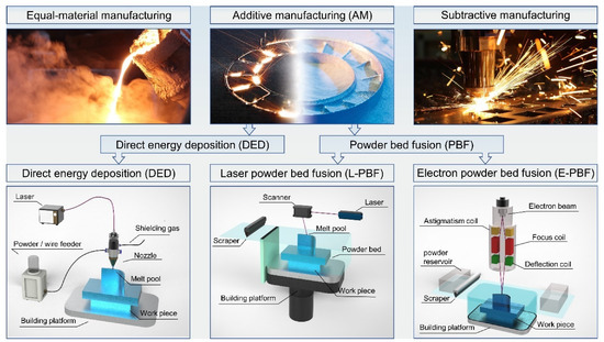
Figure 1. Classification of metal manufacturing processes: equal-material manufacturing, additive manufacturing [22], subtractive manufacturing.
Figure 1 also illustrates the forming principle of laser powder bed fusion (L-PBF), which is widely used today to rapidly manufacture parts with complicated shapes, a fine grain size, high densities, and superior mechanical properties [23,24]. Although it can currently fabricate complicated metal parts [25,26], the reliability and stability of the printing process remain inadequate [27]. There are still defects in L-PBF processing that decrease the density and affect the mechanical characteristics of the part or even result in fabrication failure. The many unresolved problems with L-PBF become a barrier to the expansion of L-PBF applications.Spatter is generated in conventional laser welding and cutting, DED, and L-PBF. Spatters are the particles ejected from a melt pool during the laser–metal interaction [28]. In conventional laser welding and cutting, the laser scanning path is relatively simple, with few overlap regions between the scanning paths, and DED has a lower scanning velocity and a larger spot than L-PBF. However, L-PBF is a powder-bed-based technology, and the printing process is more complicated than that of the three technologies mentioned above, which results in a more complex spatter behavior. Furthermore, during multi-laser L-PBF, the thermal and stress cycling, melt pool characteristics, spatter behavior, and metal vapor evolution will be definitely different from that of the single-laser PBF. The detection of spatter under multi-laser L-PBF is more difficult.
For this reason, studies on L-PBF spatter are becoming very urgent. Spatter as a by-product of L-PBF is unpreventable [29,30]. It is a detriment to the forming process, and the part and the redeposited spatters can destroy the original well-built powder layer, resulting in non-fusion defects [31,32]. Due to the uniqueness of L-PBF, the undesired effects of spatter are amplified during the layer-by-layer process. Spatter affects the subsequent re-coating and melting of the powder, resulting in internal defects in the produced part or the part failing to form.
As spatter has a significant effect on L-PBF, it can be used to represent the L-PBF machining state. Spatter contains a plethora of information and can be used in various ways to analyze the manufacturing processing of L-PBF. By observing and quantifying the spatter, it is possible to establish an intrinsic correlation between spatter and the part quality, enabling a more comprehensive understanding of the L-PBF process to solve the problems of insufficient stability and reliability, allowing this technology to be popularized and applied more widely.
Recently, the research concerning the spatter during L-PBF has received more and more extensive attention. In this work, we review academic publications concerning L-PBF spatter in the Web of Science database from 2015 to date (Topic: [“laser-powder bed fusion” and “spatter”] or [“selective laser melting” and “spatter”]). Figure 2 shows the trend in the number of articles on this topic over the last several years.

Figure 2. Number of articles about L-PBF spattering since 2016 (Topic: [“laser-powder bed fusion” and “spatter”] or [“selective laser melting” and “spatter”]) Database: Web of Science.
This article builds on previous research by reviewing a synthesis of in situ spatter detection systems, spatter detection equipment, the generation of spatter and its associated disadvantages, and current approaches for the suppression and removal of spatter. Finally, the future of research on L-PBF spatter is discussed.
2. Laser Powder Bed Fusion Spatter In Situ Detection Device
The L-PBF detection system can be categorized as: static detection (imaging of spreading powder and deformation) and dynamic detection (characterization of melt pool, spatter, and vapor plume).
The spatter generated by conventional laser welding, cutting, and DED is similar to that produced by L-PBF and is caused by the interaction between the laser and the metal material. However, L-PBF has a smaller spot (~101 to 102 µm), a smaller melt pool (up to 100 µm), a shorter lifetime (~10 ms), and a higher scanning velocity (~102 to 103 mm/s) compared to laser welding, cutting, and DED [33]. Furthermore, in L-PBF, the laser interacts with the powder bed and the metal part more than once, resulting in a greater number and variety of spatters and complicating in situ spatter detection.
The laser–powder bed interaction produces the melt pool, spatter, and vapor plume (even plasma). The trajectory of the melt pool is in the plane of the laser path and can be predicted according to the strategy path, whereas the motion of the spatter is in a 3D space, and its trajectory is complex and difficult to predict. So, the detection of spatter is more difficult. Spatter can be divided into hot droplet spatter (mainly from the instability of the melt pool) and cold powder spatter (mainly driven by the vapor-induced entrainment of the protective gas). Both of them can be detected with the visible-light camera equipped with an illumination source, and the relevant collected information can be used to analyze them.
According to various studies, the following methods are currently available for L-PBF spatter detection: (1) a visible-light high-speed camera, (2) X-ray video imaging, (3) infrared video imaging, and (4) schlieren video imaging. These detection techniques can detect different characteristics, as shown in Figure 3 and Table 1.

Figure 3. Characteristics obtained from different in situ detection techniques: (a1–a3) time series snapshots taken by visible light high-speed camera (Reprinted with permission from Ref. [34]. Copyright 2019 Elsevier B.V.); (b1–b3) high-speed schlieren images during single track scans (Reprinted with permission from Ref. [35]. Copyright 2018 Springer Nature.); (c1–c3) dynamic X-ray images showing powder motion, A is the ejected powder (Reprinted with permission from Ref. [36]. Copyright 2018 Elsevier B.V.); (d1–d3) three consecutive frames of an infrared video acquired during L-PBF (Reprinted with permission from Ref. [37]. Copyright 2018 Elsevier B.V.).