Article Content
1 Introduction
The construction industry’s productivity growth is comparatively slow in recent years, especially when measured against other manufacturing sectors (Mitterberger, 2022). A significant factor contributing to the industry’s low sustainability is its limited automation (IPCC, 2023). However, integrating digital fabrication methods into architectural and engineering design practices reveals considerable potential for enhancing productivity and minimizing environmental impacts (Dörfler, 2016).
Over the past decade, the AEC (Architecture, Engineering, and Construction) sector experiences substantial advancements in robotics manufacturing, leading to numerous new design opportunities (Cai, 2019). Despite these advancements, most research remains largely confined to academic institutions and research laboratories, where it stays at the experimental prototype stage (Liang, 2021; Soto, 2020). The working environments, materials, and processes involved are typically well-defined and predictable, resulting in linear construction processes for robots (Mitterberger, 2022).
A defining characteristic of the construction industry is the complexity of its design and construction processes (Mitchell, 2005; Dörfler, 2018). This inherent complexity renders linear and predictable robotic construction methods inadequate. Nonetheless, integrating human tacit knowledge into the precise linear cycles of robotic construction promises to leverage human intelligence to navigate these complexities (Mitterberger, 2022). This concept, emphasizing human involvement in robotic construction, is termed interactive fabrication (Willis, 2010) and is primarily facilitated through Augmented Reality (AR) technology (Kaarlela, 2022).
AR is introduced in 1997 and is defined as “the real-time integration of 3D virtual objects into a 3D real environment” (Azuma, 1997). Given that over 65% of human information acquisition comes from visual sources, the potential of AR is strikingly clear (Chen, 2019). In recent years, the practical applications of AR show remarkable promise across a variety of domains, including education, design, manufacturing, construction, and entertainment (Chi, 2013).
In architectural engineering, AR is extensively utilized (Wang, 2009). For instance, integrating Building Information Modelling (BIM) with AR leads to more intuitive project management approaches (Meža, 2014). Furthermore, AR is directly applied within digital construction processes, categorized into 3D holographic teaching, AR data sharing, and AR for facilitating human–machine interaction (Song, 2021).
Numerous studies confirm the feasibility of using AR to guide artisans in manual fabrication tasks (Mitterberger, 2020). Research also explores the role of AR in facilitating human–robot interaction during interactive construction tasks such as wood milling and assembly (Kyjanek, 2019), plastering (Mitterberger, 2022), bricklaying (Song, 2023), and grinding (Zhang, 2023; Zhang, 2024), highlighting the significant value of AR in robotic construction processes. However, in these studies, a separation exists between the design and robotic construction phases, with AR being employed for design prior to the robotic construction stage. This sequential approach does not fully leverage human intelligence in the linear robotic manufacturing process.
Integrating AR systems more extensively into robotic construction, thereby enabling greater human intervention, facilitates more intuitive and streamlined supervision and control of robots (Alexi, 2024). Existing studies on robotic wood processing explore how AR can foster more interactive settings and assist with task allocation during processes such as cutting (Kyaw, 2024), drilling (Wang, 2023), and assembly (Alexi, 2024; Rogeau, 2024). However, the accuracy of AR platforms poses significant challenges to many AR-driven manufacturing workflows (Kyaw, 2024).
Different processes have varying tolerance requirements for AR systems. Strategies to address these challenges include enhancing precision through specialized AR configuration methods (Kyaw, 2023) or minimizing the likelihood of errors introduced by AR, such as optimizing construction performance by assigning AR tasks to areas less prone to inaccuracies.
This study aims to explore the impact of higher levels of human interaction in robotic bricklaying and further examine the appropriate balance of interaction and task allocation between humans and robots in AR-assisted robotic construction tasks involving the picking and placing of large, coarse bricks.
2 Literature review
The practice of robotic bricklaying begins with the Structural Oscillations project at the Venice Architectural Biennale in 2007. Later, the introduction of a movable base expands the scope of brick wall construction (Giftthaler, 2017; Dörfler, 2016). When AR is applied to bricklaying activities, it enables the manual construction of parametric brick walls (Mitterberger, 2020). The Angelus Novus Vault project by CERCAA in Venice even demonstrates the potential for hand-crafted brick shell structures. Additionally, studies on AR-assisted robotic bricklaying have emerged (Song, 2023). However, current research often separates design from construction.
Recent research on wood fabrication explores how AR can enhance human–robot interaction during robotic construction processes. For example, the Unlog Tower project integrates gesture recognition with a mixed reality (MR) interface, advancing feedback-based human–robot collaboration. This enables the fabrication of composite materials like glued laminated timber and metal (Kyaw, 2024). However, in this study, MR primarily supports material positioning, recognition, and calibration, rather than directly assisting robotic control or task allocation.
The Cooperative Augmented Assembly project develops a mobile-based AR application linking geometric information with manufacturing attributes. This allows users to adjust task allocation intuitively throughout the fabrication process, enabling collaborative assembly of complex timber structures between humans and robots (Alexi, 2024). However, this study relies on prior structural performance simulations to ensure stability. Moreover, the lightweight timber rods used are rarely applied in real-world construction, and the significant human intervention required may not be feasible on actual construction sites.
The A-TREE project uses HoloLens GUI and ArUco markers to optimize drilling targets in real time. This MR-assisted robotic drilling setup is an important step for designing and constructing lightweight timber structures (Wang, 2023). However, this study focuses solely on robotic drilling tasks and lacks a systematic approach across the entire workflow.
In another study, timber frame assembly tasks leverage MR devices to combine human flexibility with robotic strength and precision, exploring various levels of interaction between robots and humans to achieve collaborative timber joint assembly (Rogeau, 2024). However, the fixed base of the robot limits its working range, and the size of the constructed structures is constrained. When robots and humans need to coordinate in large-scale environments with complex positional relationships, the algorithm-based task allocation methods used in this research show certain limitations.
The research presented in this paper explores AR-assisted human–robot collaboration in large-scale, mobile robotic spatial assembly. It replaces structural performance simulation and robotic obstacle avoidance path planning with human intelligence and investigates a robotic bricklaying method using large, rough bricks commonly employed in real engineering projects. Bricklaying tasks, which involve standardized materials, offer significant potential for alternating design and construction processes due to the controllable nature of the materials (Collinson, 2013). This approach utilizes human flexibility (Wang, 2023) while harnessing the precision and labor substitution capabilities of robots, freeing humans from hazardous tasks and enabling them to engage in creative processes (Takayama, 2008). Consequently, AR-assisted robotic brick construction holds considerable potential for development.
To deepen the level of interaction between humans and robots and maximize human intelligence in linear robotic tasks, this study conducts a comparative experiment using bricklaying tasks. It compares two interactive construction methods: “design after construction” and the more interactive “alternating design and construction.” The experiment analyzes changes in construction goals, experiences during the process, and the accuracy of results as interactivity increases.
Building on the findings from this experiment, this research completes the design and construction of a parameterized brick wall with an 8-m-long sloped pattern. This method neither follows “design after construction” nor “alternating design and construction.” Instead, while the design is pre-completed, it is adjusted during highly interactive construction to create a form better suited to the environment and with improved structural performance.
In conclusion, this study discusses how to allocate specific tasks during design and construction between humans and robots in highly interactive activities. It assigns functions based on the strengths of human flexibility and robotic precision under high loads, establishing a more effective robotic construction method.
3 Methodology
This research develops an enhanced interactive construction workflow. The workflow is first applied in a comparative experiment between general and enhanced interactive bricklaying, where two methods with varying degrees of interactivity are used to design and construct a parametric brick wall (Zhang, 2025). Based on the conclusions of the experiment, the workflow’s level of interactivity is adjusted by reallocating the roles of humans and robots in the process, followed by the construction of a large-scale brick wall using real engineering bricks. While the comparative experiment and the construction case study follow a similar workflow, they use different software, hardware, and construction materials.
3.1 Comparative experiment setup
The experiment materials included several small-scale wooden blocks (80 mm * 40 mm * 20 mm) and a brick-feeding ramp device.
For hardware, the primary tools used were an iPhone 8 Plus and HoloLens 2 as the input and output devices for augmented reality. A Schunk pneumatic gripper was employed to grasp the bricks, operated by a UR10e robotic arm. Additionally, a laptop was used to adjust and connect all the devices. All devices were linked to the same IP address within a shared Wi-Fi router network.
Regarding software, the experiment was conducted using Rhino and Grasshopper as the primary platforms, alongside the Robots and Fologram plugins. Robots was used to control the robot’s movement path, speed, and types of motion, as well as to send script commands for opening and closing the gripper. Fologram was used to project virtual 3D models onto the hardware devices and to recognize user inputs generated through hand gestures or screen taps.
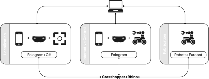
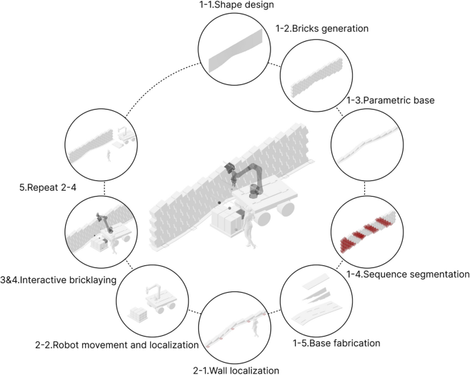
The tasks completed in the experiment can be generally categorized into three types: localization, interactive design/control, and fabrication. The software and hardware used to accomplish each task type are shown in the following figure (Fig. 1).
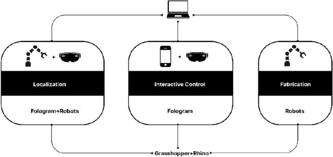
Localization primarily involved the use of robots and HoloLens via the Fologram and Robots plugins. Interactive control/design mainly utilized HoloLens and iPhone via the Fologram plugin. Fabrication primarily employed robots via the Robots plugin
3.2 Construction case setup
For construction materials, large-scale engineering bricks (300 mm * 250 mm * 190 mm) were used, with each brick weighing 13 kg. Additionally, a parametric base (Fig. 2) was fabricated using CNC-cut wooden panels to enable the inclined pattern of the brick wall. To facilitate brick feeding for the mobile robot, a movable pallet was constructed to move in sync with the robot. A custom marker from FANUC was placed on top of the pallet to help the robot’s vision system determine the relative position of the robot’s base coordinates.
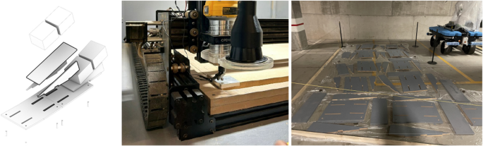
Configuration of parameterized base (left), CNC machining of parameterized base (mid), Painting of parameterized base (right)
Specifically, the hardware configuration of this system can be divided into the rover, the robot, the computer vision system, and the AR interaction system.
The robot system is centered around the collaborative robotic arm Fanuc CRX-25iA, which has a maximum payload capacity of 30 kg and a maximum reach of 1890 mm. The robot controller used is the Fanuc R-30iB Mini Plus, while the end-effector is the Schunk EGU 60-IL-MB, capable of force control up to 1300 N and millimeter-level precision in travel control (Fig. 3). Due to the use of large-scale engineering bricks, each of which is heavy and has a rough surface, robotic assistance in handling the bricks reduces the risk of injury to workers. The large size and heavy weight of the bricks are typically beyond the capabilities of most collaborative robots and electric grippers. Therefore, the hardware used in this study is designed with higher specifications to meet these demands.
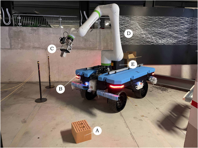
Robot system configuration: (A) Engineering bricks, (B) Rover, (C) Schunk EGU 60-IL-MB, (D) Fanuc CRX-25iA, (E) Fanuc R-30iB Mini Plus
The rover, integrated by Sigma Engineer, features a dual control system comprising manual remote control and autonomous navigation. Its power system consists of four independently driven wheels and individual steering motors, enabling various types of movement: traditional four-wheel steering, parallel wheel movement for precise translational motion, and in-place rotation with zero turning radius for changing direction (Fig. 4). Compared to other locomotion types, such as tracked systems, this method is more flexible and efficient; however, the stability of the rover decreases under high payload conditions. The rover is also equipped with LiDAR sensors and stereo cameras (Fig. 5), which can be used for point cloud mapping or object detection in the environment. Since the construction was carried out at an exhibition, the limited space and high foot traffic made the aforementioned more flexible and safer type of rover the optimal choice.
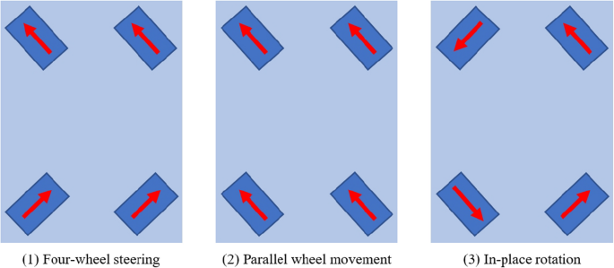
Three types of rover movement
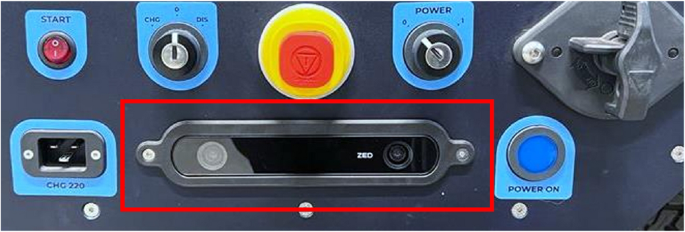
Stereo cameras on rover
The computer vision system utilizes the Fanuc iRVision 2D vision system (Fig. 6), which achieves precise spatial calibration by detecting the displacement of the camera coordinate system through recognition of FANUC-customized marker codes. Overall, the computer vision system in this study serves to enhance the accuracy of augmented reality by providing corrective adjustments.
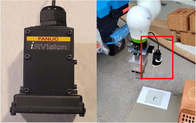
iRVision 2D camera (left), Installation of camera on robot (right)
The AR interaction system employs an iPhone 8 Plus and HoloLens 2 as augmented reality input and output devices. The HoloLens 2 integrates an environmental camera, IMU (Inertial Measurement Unit), and depth sensor to enable spatial positioning, gesture tracking, and object recognition.
For software, the setup relied on Rhino and Grasshopper, using the Robots, Furobot, Fologram plugins and custom C# components. Robots and Furobot were used to simulate and control the robot’s movement path, speed, and motion types, as well as to integrate robot and PLC script commands for controlling the gripper and the computer vision system. Custom C# components were used for communication between the computer and robot PLC. Combined with the Wi-Fi on the rover and the relevant configurations pre-set on the robot PLC, this enables bidirectional reception and transmission of various data between the Grasshopper platform and the robot. The relevant configurations on the robot PLC were implemented by Sigma Engineer as part of the rover’s setup. Fologram was utilized to project virtual 3D models onto the hardware devices and to detect user inputs generated through hand gestures or screen taps. Fologram can convert user interactions with virtual geometries into changes in Boolean values, which are then used as input values for C# components. This allows the user interaction behavior to control the robotic motion.
The tasks in the case study, similar to the comparative experiment, were categorized into three types: localization, interactive design/control, and fabrication. The software and hardware used for each task type are illustrated in the following figure (Fig. 7).
Localization involved the use of computer vision system and AR devices via the C# component and the Fologram plugins. Interactive control mainly utilized AR devices and robot via the Fologram plugin and the robots/furobot plugin. Fabrication employed robots in same way
Regarding safety protocols for accident prevention during operation, the rover adheres to the European autonomous vehicle safety standard (EN3691-4, 2023). A safety laser scanner is installed on the rover to detect potential collision risks, ensuring it stops before colliding with other objects. The robot, as a collaborative robot, complies with the (EN ISO10218-1, 2025) standard and the technical specification (ISO/TS15066, 2016), allowing it to work alongside humans in the same shared space without the need for additional protective measures.
4 Comparison experiment between conventional and enhanced levels of interaction
4.1 Preparatory operations
Before initiating the process, it is crucial to align the AR environment with the physical setting and establish a reference plane. The alignment begins by manually adjusting the robot’s Tool Center Point (TCP) to coincide with the reference plane. A custom component is then used to relay the TCP’s current position back to the computer, where the data is saved. By repeating this process at several points along the reference plane, the system calculates its exact position. The alignment between the virtual and physical environments is generally achieved by placing a QR code at a designated location, which the AR device recognizes (Fig. 8). Additionally, Fologram offers manual fine-tuning options in its settings to enhance precision.
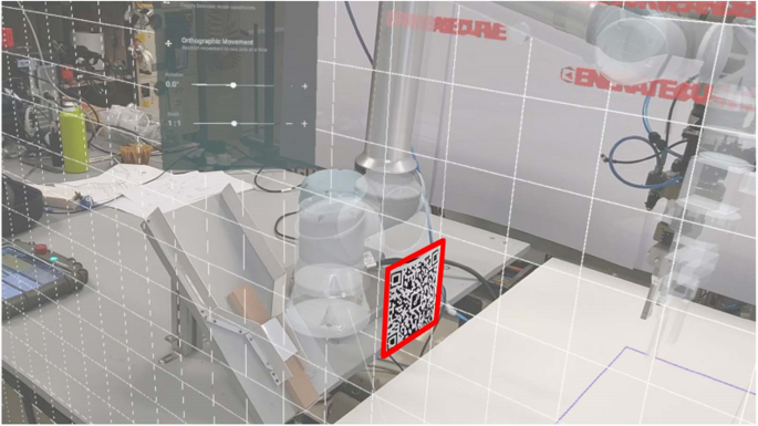
Align virtual and real environments by scanning QR codes and manually align virtual and real environments
To minimize errors from overly sensitive AR gesture recognition, the entire workflow is divided into distinct steps. Only the AR recognition for the active step is enabled at any given time. To switch between steps, a series of interactive virtual buttons were created for this study, each labeled with its respective function. A red button indicates inactivity, while green indicates an active state (Fig. 9).
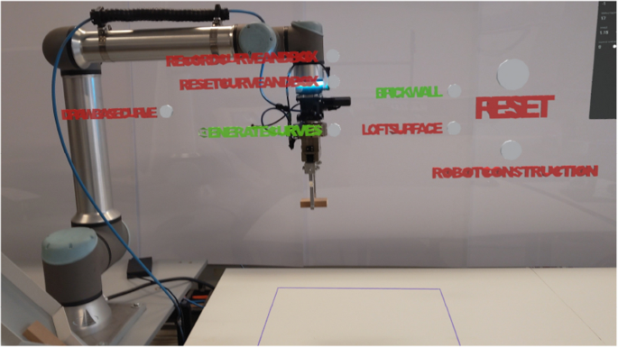
AR button controls switching between asynchronous steps
4.2 Conventional level of interaction
In the interactive control phase (Fig. 10), the process unfolds as follows: (1) The user begins by drawing a basic curve using hand gestures, with the HoloLens tracking the hand’s movement and recording a series of points. The curve is then generated by connecting these points. (2) After the curve is created, the user can refine its shape by manipulating control points along the curve. (3) A second curve is automatically generated at a specified height, which, together with the initial curve, forms a surface through lofting. This newly created curve also has adjustable control points, allowing further customization of the surface’s shape. (4) Once the surface is satisfactory, a parametric brick wall, consisting of bricks sized accordingly, is automatically generated based on the surface. Users can preview the brick wall and continue to adjust its shape or parameters, such as brick spacing, by moving control points until the final configuration is reached. (5) When the design phase is complete, the user clicks the “construction” button to initiate the robot’s operation.
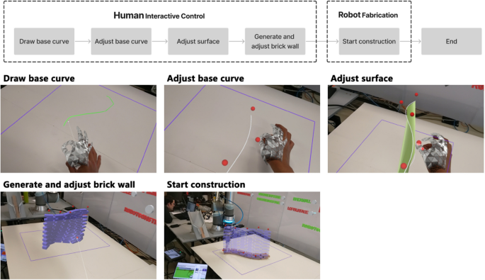
The design and construction process of conventional interaction level
4.3 Enhanced level of interaction
In enhanced interactive construction, the control and construction phases alternate layer by layer (Fig. 11): (1) The process begins in the interactive control phase, where the user draws the initial curve using gestures. (2) The curve’s shape is then refined by adjusting control points. (3) Based on this curve, bricks for the current layer of the wall are generated, and parameters such as brick spacing are adjusted. (4) Once confirmed, the robot places the bricks in their designated positions. (5) After construction of a layer is complete, the system registers the built layer and generates the next layer of bricks in augmented reality. By default, each new layer starts with the same configuration as the previous one. (6) The user can then observe the built portion, adjusting the shape of the new layer by manipulating control points and repositioning bricks to ensure that changes to the wall’s form do not compromise its structural stability. This demonstrates the value of human input in fine-tuning the otherwise linear robotic construction process. (7) Once the new layer is adjusted, the construction continues, with this cycle repeating until all layers are completed.
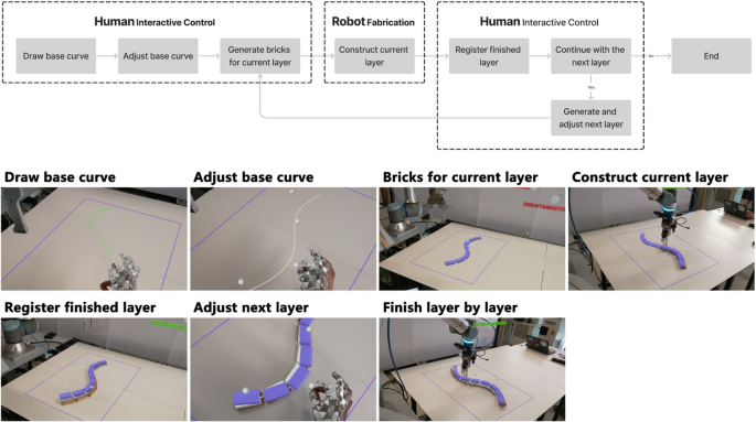
The design and construction process of enhanced interaction level
4.4 Discussion of comparison experiment
To compare the characteristics of varying interaction levels in construction methods, this study conducted a qualitative analysis of the two approaches. Data collection and evaluation were conducted using the method of participatory observation. The authors, along with two other researchers with backgrounds in architecture and robotic construction, used the system to complete the construction tasks. Based on their observations of the robots’ performance and the construction outcomes during the process, they collaboratively discussed the differences between the two methods. The analysis focused on key aspects such as the types of construction goals, the experience of the construction process, and the accuracy of the final results (Fig. 12).
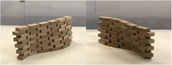
The construction results of conventional interaction level method (left) and enhanced interaction level method (right)
In terms of construction accuracy, the conventional interactive method, which evenly divides the surface into regularly spaced positions for each brick layer, leads to consistent variations with neatly aligned brick shifts. In contrast, the enhanced interactive method, where shape adjustments between adjacent layers are manually controlled, produces more unpredictable results in terms of accuracy.
From the perspective of user experience during the construction process, the conventional interactive method combines immersive AR-based design with fully automated robot construction. In some cases, structural simulations are required beforehand to ensure stability. On the other hand, the experience of the enhanced interactive method differs significantly, as each layer’s shape is individually determined. This process is less efficient but allows for greater user involvement and control over the construction.
Regarding the types of construction objectives, the conventional interactive method is particularly well-suited for linear parametric brick walls, where precision is critical and the robot’s accuracy can be fully leveraged. Conversely, the enhanced interactive method is less appropriate for such tasks. Excessive human intervention reduces construction accuracy, leading to suboptimal gradient effects in linear brick walls (Table 1).
Based on the above comparative analysis, several key insights can be drawn: First, predefining the shape design is essential to achieve a cohesive overall form. Second, to enhance user engagement during the construction process and thereby reduce the need to account for uncertainties during the design phase—such as determining placement sequences and ensuring structural stability in complex patterns—adopting an interactive control logic during construction is necessary. Finally, to further demonstrate the benefits of a more interactive robot control method, it is crucial to build more complex brick patterns and to complete large-scale 1:1 construction using real materials. Consequently, this study proceeded with a follow-up construction case.
5 Construction case
This construction case presents an AR-assisted method for laying bricks using a mobile robot to construct an inclined-pattern brick wall. The system is an interactive mobile robot brick-laying approach, where the wall’s form is pre-designed. Architects and workers can leverage human flexibility by using gesture-based controls to intuitively guide the mobile robot in executing large-scale brick-laying tasks on-site. This method replaces the need for structural stability simulation when the structural complexity is low, as well as the automatic planning of the robotic obstacle avoidance movement path, by incorporating human intelligence into the process.
Based on the conclusions drawn from the comparative experiments in the previous section, this construction case set the task as constructing a full-scale brick wall using large-sized engineering bricks. Unlike the experimental bricks used in other studies, each brick in this instance weighs 13 kg, has a rough and uneven surface, and exhibits low standardization, making it difficult to handle manually. Additionally, the bricks are placed on a parametric base, forming a unique inclined pattern, and the wall is constructed through dry stacking without the use of mortar. The wall spans 7 m in length and reaches a height of 1.8 m. The large-scale construction further requires the robot to move continuously and reposition itself accurately multiple times.
To achieve these objectives, the system was improved in three key aspects: the development of a large-area localization system that integrates AR with computer vision technology for complex environments, the transformation of the AR control interface from 2D buttons to a 3D spatial interaction interface, and the deployment of a higher-load collaborative robot paired with a mobile base equipped with autonomous sensing capabilities (Fig. 13).
The enhanced interactive bricklaying system
5.1 AR based localization and control system
In this project, an AR-based operating system was primarily used to achieve localization and control functions. By tracking QR codes, the positions of the robot, wall, and pallet in the real world were transferred into the virtual world in the computer. Considering the construction scenario in this paper, in order to ensure that the QR code is neither too small to be accurately recognized nor too large to obstruct the construction process, its size is set to a square with a side length of 18 cm. Additionally, the system provided a virtual interactive interface through which users could select bricks to pick and place, make fine adjustments to the brick positions, define intermediate points to avoid singularities, and control different stages of the robot’s operation.
5.1.1 AR-based localization
The QR code recognition and localization system used in this project employed two methods for positioning. The first method aligned the virtual world coordinates with QR codes in the real world, while the second method imported the coordinates of the real-world QR codes into the virtual world.
Both methods rely on the Fologram plugin platform, which locates multiple markers within a given workspace or on the workpiece, providing well-defined spatial location data to enhance the accuracy of holographic projections in AR. Kyaw et al. provide a detailed explanation of the workflow of this method (Kyaw, 2023; Pollefeys, 2018). The Twinbuild plugin they used is developed based on the same technology and principles as Fologram, utilizing algorithms based on native HoloLens 2 SLAM to position a virtual camera in any Cartesian space, ensuring that the digital 3D environment remains fixed relative to the moving HoloLens. Additionally, The CAD integrations are used to determine the coordinates of markers (QR codes).
For the first method, QR codes were created at several coordinate points in the virtual 3D environment on the computer. Once created, the generated QR codes were printed and accurately fixed at corresponding positions in the physical world. When the AR device’s camera detected a QR code, the corresponding virtual coordinate was aligned with it. In this project, the wall and pallet were localized using this method.
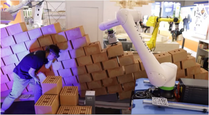
For the wall localization, six QR codes (b1 to b6) were used, with one QR code placed at the corner of every two base sections. The base sections are created through precise CNC cutting, and during on-site assembly, they are calibrated with a level. The alignment of the QR code with the base ensures the accurate relative position between the QR codes. These six QR codes are evenly distributed along the wall, which ensures that the virtual wall was aligned with the physical wall, and regardless of where the user moved along the wall, there was always a QR code available for recognition, maintaining stable alignment (Fig. 14).
Align virtual and real walls by identifying QR codes at specific positions in wall corners (left), Position of QR codes: (A) Wall to align, (B) Parameterized base (right)
The second localization method involves first printing QR codes with corresponding identifiers, and then using an AR device to recognize the numbered QR codes. When the device detects a specific QR code, it imports the coordinate information of that QR code into the virtual environment. In this project, this method was used for the localization of the pallet and robot.
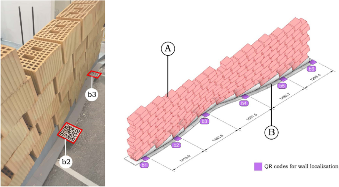
For pallet localization, several QR codes such as “p1” were utilized. The QR code is fixed at the corner of the pallet near the user’s side, ensuring that it will not be obstructed by the bricks, preventing it from being unrecognizable. As shown in the diagram, various positions parallel to the wall were designated as pallet locations for feeding bricks to the robot. The diagram provides three representative positions. When the pallet is moved to different locations, scanning its QR code allows the system to obtain the pallet’s precise location (Fig. 15).
Determine pallets’ position by identifying QR codes (left), Position of QR codes: (A) Pallets to track, (B) Bricks to be used, (C) Support for computer vision marker (right)
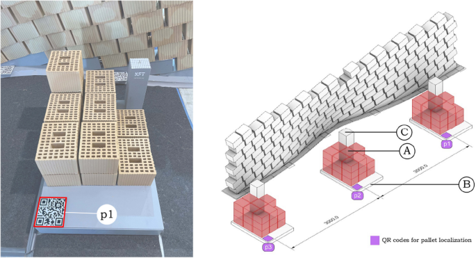
To more precisely localize the robot’s position, four QR codes (r1 to r4) were placed on the mobile base in this project to determine the robot’s root plane. Furthermore, the four QR codes are evenly fixed around the robot on the aluminum profile extension strips of the rover’s cover plate. This method requires accurately measuring the spatial relationship between the robot’s root plane and the four QR codes, ensuring that the robot’s position can be accurately imported into the virtual environment (Fig. 16). During the construction of the rover, the aforementioned considerations were taken into account. The rover was designed and assembled using an information model, with aluminum profiles added to the cover plate for expansion. Markings were made on the aluminum profiles according to the corresponding positions of each QR code.
Determine the robot’s position by identifying QR codes (left), Position of QR codes: (A) Robot, (B) Rover to track (right)
It is important to note that the localization of the base is closely tied to its movement control method. For the functional design of this base, it is possible to pre-assign parameters, such as movement speed or direction on various segments (Ruttico, 2024). In such cases, the base’s movement is guided by a planning algorithm (Park, 2007), which detects obstacles in real time during movement and controls the base accordingly. However, in this study, the base’s movement was primarily controlled manually, with the method mentioned above serving as an auxiliary approach. The base was manually positioned at different stages of the construction process.
5.1.2 Computer vision system for correcting localization
Although AR-based localization is theoretically highly feasible, small drift issues with AR still persist, particularly in complex environments with significant changes. Additionally, the mobile base uses flexible wheels, which can also introduce errors. Therefore, to ensure complete precision in construction, the AR-based localization must be further corrected to its exact position. To achieve this, the Fanuc irVision 2D vision system and a computer vision alignment program based on FANUC custom marker codes were used. Sága et al. provide a detailed description of the configuration and usage of the Camera Calibration Tool, known as the “Two-plane method” (Sága, 2020). The operating principle of this system in the present study is described as follows.
In this study, the robot coordinate correction process based on the Fanuc iRVision 2D system primarily involves the marker, camera, and robot’s coordinate systems (Fig. 15):
•F: Marker coordinate system (fixed, reference coordinate system).
•W: Wall coordinate system (fixed, reference coordinate system).
•Cideal: Camera coordinate system (the relationship with the robot position remains unchanged before and after offset).
•Cactual: Camera coordinate system after offset.
•Rideal: Robot coordinate system (shifted due to movement).
•Ractual: Robot coordinate system after offset.
In the ideal case, the coordinate relationship between the camera, robot, and marker is described by the following equation:
•TRFideal: The ideal transformation matrix between the robot and the marker.
•TRC: The fixed transformation matrix between the robot and the camera (constant and unchanged).
•TCFideal: The transformation matrix between the camera and the marker in the ideal state (known).
When the robot undergoes a shift, the Fanuc iRVision 2D system identifies the transformation relationship TCFideal between the camera and the marker after the shift. At this point, using the fixed relationship TRC between the camera and the robot, the transformation relationship between the shifted robot and the marker can be calculated:
•TRFactual: The transformation matrix between the shifted robot and the marker (desired computed result).
•TCFactual: The transformation matrix between the camera and the marker after the shift, as identified by the vision system.
Throughout the process, due to the fixed physical connection between the robot and the camera, the transformation relationship TRC between the robot and the camera remains constant. This relationship allows the offset correction process to efficiently compute the new robot coordinate position by real-time updating of TCFactual, thereby enabling efficient correction of the robot’s offset (Fig. 17).
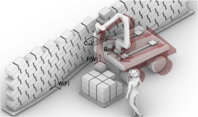
Coordinate transformation in correcting offset in computer vision systems
To use this program, a special QR code must first be fixed on the pallet (Fig. 16). It is important to note that this QR code must maintain an accurate relative position to both the wall and the pallet. Since the pallet has already been set at a fixed relative position to the wall, fixing the special QR code at the corner of the pallet ensures that its relative position with the other two elements remains unchanged.
In practice, the first step is to designate the point where the marker is located as the initial target point in the robot’s movement path, followed by setting a pause. Then, the corresponding script code is inserted to activate the alignment program. Although the AR localization system has minor inaccuracies, the robot can still move very close to the marker’s location even without alignment (Fig. 18). At this point, the camera captures the position of the marker. Through algorithmic analysis, the robot’s TCP is adjusted to precisely align with the marker. Simultaneously, the entire coordinate system (pallet and wall) is aligned with the corresponding real-world objects as the TCP aligns with the marker.
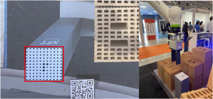
Marker for computer vision system (left), Position to start alignment program (right)
This method is relatively easy to implement. However, it is crucial to ensure the exact relative positioning between the wall, pallet, and QR code, which is also the main limitation of this system.
5.1.3 AR-based mobile robot control system
Using the AR system, this project created a spatially interactive virtual user interface. Through this interface, users can intuitively complete a series of tasks during the construction process using gestures. These tasks include step-by-step selection of bricks, fine-tuning the pick-and-place positions, making the robot’s work process more controllable. There are two types of control methods, blue for gesture operation control and green for virtual button control (Fig. 19).
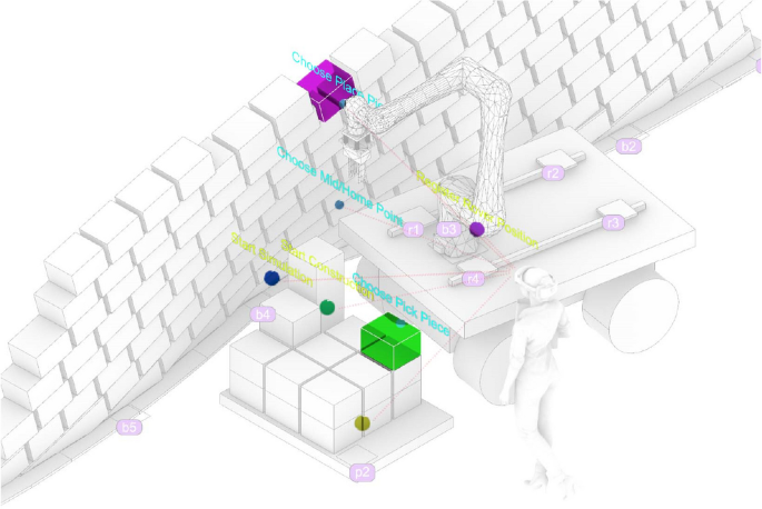
AR based virtual system with 6 functional cursor elements
Using gesture controls, users can select which bricks to pick up and define where to place them. Additionally, intermediate points and the home position can be defined through gestures, thereby establishing the robot’s movement path in a pick-and-place cycle. This method eliminates the need for pre-programming to ensure that the picking and placing operations follow a sequence without repetition or omission. Instead, the operator can determine the positions for each operation in real-time.
By using virtual buttons, the robot and the pallet can be re-registered after each movement of the rover. Moreover, the start and end of robot tasks can be controlled, and before actual execution, the virtual robot’s movement path can be previewed to check for potential collisions or errors. This setup effectively addresses various risks associated with robot movement, such as singularities, collisions, and issues with reachability.
It is important to highlight that the control points for the brick placement (choose place pieces) are not only used to select the position where the bricks will be placed but can also be dragged to fine-tune their position after an initial click. This feature is necessary because certain sections of the wall exhibit significant changes in slope (Fig. 20), and since the structure has not undergone stability simulations and the bricks are rough, human inspection and adjustments during construction are required to ensure stability. As a result, the final built structure may differ to some extent from the original design.
Wall’s significant changes in slope (left), AR assisted manual inspection and adjustments (right)
5.2 The entire workflow
To build a special style brick wall using the interactive mobile robot control system mentioned above, these steps need to be followed (Fig. 21):
Workflow of the system
5.2.1 Design of form, base construction, and consequence of brick groups
As previously mentioned, the first step involves designing the brick wall, determining the exact placement of the bricks, and constructing the base. However, an equally crucial step before starting the construction cycle is analyzing the order in which the entire wall will be built. Given that the wall is composed of inclined bricks, the sequence in which the bricks are placed is more strictly constrained (Fig. 22). There are various ways to approach the construction, and this study adopts the method illustrated in the figure below.
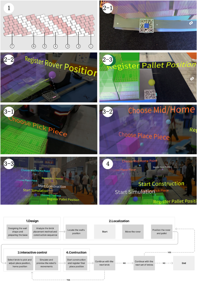
System walkthrough: (1) Divide bricks into groups, (2–1) Locating the wall’s position, (2–2) Positioning the rover, (2–3) Positioning the pallet, (3–1) Fine tune the picking position, (3–2) Fine tune the placement position, (3–3) Start simulation, (4) Start construction
The placement of bricks within each major construction cycle is primarily limited by two factors: the position of the already placed bricks and the reachable area of the robot’s TCP. The chosen method, as shown in the diagram, features the robot moving from one end to the other without the need to backtrack. Under these multiple constraints, the wall’s sections display a distribution pattern where the ends are more clustered, while the middle section is more linear.
It is important to note that the distribution plan shown in the figure represents an ideal scenario. This configuration serves as the standard for guiding the robot’s movements in subsequent steps. However, there may be deviations during actual operation, requiring human interactive control to complete the construction tasks effectively.
5.2.2 Moving and Localization of Walls, rover and pallet
5.2.2.1 Wall positioning
To position the wall in the virtual environment, use a head-mounted AR device or a mobile device to scan the QR code located on the base). This action brings the wall into the virtual world for further interaction and alignment.
5.2.2.2 Moving the rover and pallet
According to the pre-planned strategy, move the rover to the designated working position and check whether its reachability is within a reasonable range. If not, continue repositioning the rover. Next, place the pallet in its corresponding location and accurately measure its position relative to the wall base to ensure that it aligns with the position in the virtual environment.
5.2.2.3 Localizing the rover and pallet
After confirming that everything is correct, use the AR device to scan the four QR codes on the rover. Once recognized, click to register the rover’s position in the virtual environment. Next, scan the QR code on the pallet to check the alignment between its virtual and real-world positions, and then register the pallet’s location.
5.2.3 Interactive control process
5.2.3.1 Setting the TCP motion path
By selecting the bricks to be picked up and placed, as well as the intermediate points, the motion trajectory for a single robot operation is programmed.
5.2.3.2 Adjusting the placement of bricks
By observing the current degree of inclination of the wall, click on “choose place piece” and then drag to fine-tune the position of the bricks, reducing the curvature to enhance the structural stability. Due to the low accuracy of manually adjusting the brick positions, during construction, there were instances where after adjustments, the brick placement was either higher or lower than the actual position, which could cause the robot to stop due to excessive force. This can be optimized by introducing constraints on the movement of the bricks in the horizontal or vertical direction, allowing the bricks to only move within the horizontal or vertical direction of their own coordinate system during fine adjustments.
5.2.3.3 Simulating and initiating robot motion with registered brick placement
Use the virtual UI buttons to initiate a simulation of the robot’s movement and check for any potential collisions or other issues.
5.2.4 Operation and recording of bricks
Once confirmed, the robot can be set to operate. After each brick is placed, its adjusted position will be recorded, and the overall shape of the surface will change accordingly, ensuring a cohesive placement for subsequent bricks.
5.2.5 Starting or ending the cycle
If there are additional bricks to be placed within the current group, return to step e to begin the cycle again. If a group has been completed, proceed to step c to relocate the rover to a new position. This process continues in a loop until the construction is fully completed (Fig. 23).
Construction completed
6 Result and discussion
Throughout the construction process, human intervention played a critical role in recognizing uncertainties and making continuous adjustments to the robot’s operations using the interactive system. This dynamic interplay between human input and robotic execution ultimately resulted in the construction of the wall. At areas with high curvature, brick positions were adjusted to ensure structural stability. To further analyze this, the final positions of each brick were introduced back into the virtual environment and compared with the original design surface. The figure reflects the magnitude of the displacement distance through color coding (Fig. 24). Additionally, the distribution of displacement distances for each brick has been compiled (Table 2). Most bricks have a displacement distance within 25 mm, while the average displacement distance for all bricks is approximately 34 mm (Eq. 1).
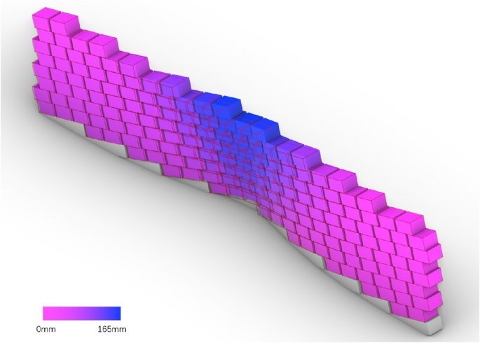
The magnitude of the displacement distance through color coding, with significant offsets mainly located in the middle section
It can be observed that, with human adjustment, the shape of the wall has undergone significant changes, with the most noticeable changes occurring in the middle part of the wall where the curvature is more pronounced. This is because, in the original design, the curvature was relatively small on the sides, resulting in a structurally sound design, whereas the curvature in the middle part was excessively large, creating obvious structural issues. During the construction process, the user subjectively reduced the curvature, with the original design transitioning from a curved bottom edge to a straight top edge. However, the final construction result still shows some curvature in the top edge. The gap between the design intent and the construction outcome highlights the role of human expertise in maintaining structural stability, especially in the absence of pre-simulation.
During the comparative experimental phase, this study conducted demonstrations and tests with approximately 20 professionals from the Italian AEC industry (Fig. 25).
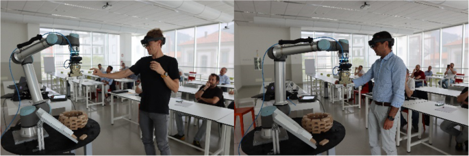
The subjects attempted to use this workflow to complete a construction of an instance
Most participants were able to immediately use the system to guide the robot in completing a brick pick-and-place task after a brief introduction. A few participants were unable to complete the task due to their inability to perform the gestures required by the system, which led to the AR system failing to recognize the input commands. The difficulty in completing the task was directly related to the participants’ age, with those unable to complete the task being older. To address this issue, it may be considered to use a controller as an alternative to gestures for performing complex operations.
Overall, the training process for the system is simple and easy to grasp quickly. Multiple participants successfully used the system to complete the design and robotic construction of a circular brick wall, demonstrating the role of the AR system in facilitating human involvement in robotic construction and enhancing interactivity.
In their evaluations, participants generally believed that this AR-based human–computer interaction construction method has the potential to drive automation development within the industry. However, they expressed concerns about its immediate applicability in real construction scenarios. The reasons for this include various complexities, such as: insufficient accuracy of AR devices; uncertainty regarding the meaningfulness of human intervention in robotic construction processes; the potential impact of increased interactivity on the aesthetic quality of wall parametrization; the experimental setting not replicating real construction environments or utilizing authentic building materials; and the method being in a prototype stage, which only offers a glimpse of its possibilities.
In subsequent construction instances, this study addressed relevant issues by integrating experimental results and demonstration feedback. For example, it emphasized the importance of completing the design phase prior to construction while simultaneously making small adjustments based on real-time conditions during the building process. The study also utilized a computer vision system to achieve precise alignment between virtual and real objects, replacing structural performance simulation under low structural complexity conditions and robotic base’s path planning with human intelligence, and employed rough materials used in real construction to realize a 1:1 scale design.
However, due to time and space constraints, this study still faced certain limitations: a. Insufficient optimization of the user interface (UI). In the current experiment, guidance was provided to the users simply through text; b. The construction workflow not being fully optimized and simplified; c. Many bricks could not be placed by the robot due to height limitations, necessitating manual assistance for brick placement; d. The need for custom bases to accommodate the sloped patterns, resulting in limited flexibility.
Based on the aforementioned limitations, the future directions of this research are outlined as follows. First, explore more application scenarios where human involvement in the linear robotic construction process can leverage human intelligence. Second, attempt to apply AR in other types of robotic construction tasks to enhance interactivity and analyze its effects. Third, improve the aesthetics and effectiveness of the UI interface to enhance system completion. Specifically, the following measures could be considered: a. Design individual icons for each function to replace text (Kyaw, 2023; Amtsberg, 2021). b. Introduce multimodal guidance methods, such as voice assistance (Mitterberger, 2022), to facilitate autonomous user interaction. c. Group buttons and labels according to the workflow and make them appear only in the relevant stages to avoid confusion.
It should be further clarified that the augmented reality construction tool used in this study is Fologram, based on the Rhino and Grasshopper platforms. This plugin was mainly designed to assist manual construction, which means the augmented reality functions provided by Fologram alone are sufficient to complete the construction. However, when augmented reality is used to assist robotic construction, the human–robot interaction system consists of the Robot Operating System (ROS) and the augmented reality system. The communication functionality needs to be integrated within the system, and the UI becomes more complex (Walker, 2023). To achieve a more stable and adaptable human–robot interaction system, developing customized augmented reality platforms tailored to collaborate with ROS, using platforms such as Unity, could be a potential direction for future development. For example, in the case of CompasXR (Alexi, 2024), the platform should customize the UI according to the interaction characteristics of the augmented reality devices used, such as mobile devices and head-mounted displays, and establish more stable communication methods based on the ROS employed.
7 Conclusion
By comparing the application of AR technology in robotic construction with conventional methods, this study proposes an innovative interactive construction approach aimed at enhancing interactivity. This method involves collaborative interactions between humans and robots during the construction process, creating a new paradigm characterized by the alternation of human intelligence and robotic precision. A comparative experiment involving the placement of wooden blocks demonstrated the potential of this method to enhance the adaptability and creativity of construction systems.
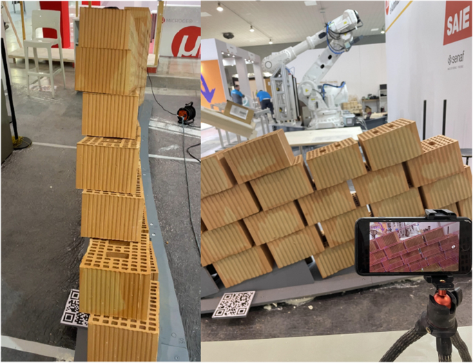
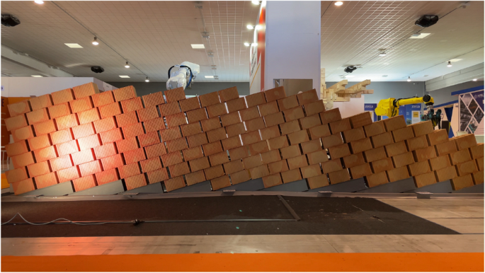
Subsequently, the feasibility and effectiveness of AR in facilitating human intervention in robotic construction were further validated through the implementation of an interactive brick wall construction case. This project employed a highly interactive AR system, allowing for a reallocation of tasks between humans and robots. It successfully constructed a 1:1 scale brick wall made of large engineering bricks, featuring an inclined pattern and constructed without mortar (Fig. 26). By analyzing the roles played by AR and human intelligence in replacing performance simulation of simple structures and robotic obstacle avoidance path planning, the study further underscored the positive implications of enhanced interactive construction and the differences between design and construction outcomes.
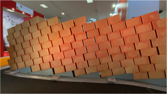
The final construction effect of the wall
The results of this research not only contribute to enriching the field of robotic construction but also introduce an innovative digital manufacturing approach within the architectural engineering sector. AR-assisted robotic construction enhances the intelligence of buildings and fosters a more direct and interactive collaboration between humans and robots. As technology continues to advance, this method is expected to have a profound impact on the construction industry, paving the way for new possibilities in digital construction and smart buildings. Consequently, this research provides valuable insights for the future development of the AEC industry, offering a viable method for seamlessly integrating intelligence and creativity of human with accuracy and reliability of robot.