Article Content
Introduction
The construction industry faces considerable challenges, including inefficiencies, excessive energy consumption, and negative environmental impacts, underscoring the urgent need for innovative approaches to sustainable building practices [1, 2]. These issues are largely attributed to factors such as low productivity [3,4,5]. In response, the adoption of off-site construction (OSC) methodologies has proven effective in enhancing efficiency across construction projects [6]. In Canada, a survey conducted by the Association de la Construction du Québec (ACQ) (2020) reveals that 41% of industry experts recognize Off-site Construction (OSC) as a key approach to significantly lowering overall project costs.
While digital technologies like Building Information Modeling (BIM) have the potential to significantly improve productivity in construction, research on construction automation has largely focused on the design phase.
This study aims to address these challenges by integrating Building Information Modeling (BIM) and robotic fabrication to enhance the design and execution of sustainable building façades in Off-site Construction Manufacturing (OSCM).
The primary objective of this research is to develop a parametric methodology that leverages BIM and robotic fabrication to optimize façade designs, focusing on minimizing solar radiation and façade area while meeting energy efficiency and sustainability criteria. The study is motivated by the need to overcome the limitations of traditional construction methods, particularly in manufacturing free-form façade components, which are labor-intensive and time-consuming due to their complex geometries.
The problem statement centers on the inefficiencies inherent in traditional construction practices and the industry’s struggle to adapt to more sustainable and efficient methods. By proposing a novel operational methodology, this research seeks to streamline the design and fabrication process, thereby improving precision, reducing labor intensity, and enhancing the adaptability and efficiency of OSC workflows.
In conclusion, the following literature review will explore existing research on BIM, digital fabrication, and sustainable design, setting the stage for a detailed examination of the proposed methodology and its potential to transform industry practices.
Literature review
Off-site construction manufacturing
In literature, Off-site manufacturing (OSM) refers to the use of digital technologies including software and hardware in OSC. This combination is introduced as Off-site Construction Manufacturing (OSCM) in this research. It is becoming significantly important to increase efficiency which is based on quality employing manufacturing techniques in a controlled factory environment applying a lean philosophy toward innovation in Off-site projects [7]. Industrialized Building System (IBS) is an effective solution based on Off-site projects to overcome poor productivity in the construction industry [8]. However, many construction players including designers and developers are facing problems selecting suitable IBS for applications in construction development projects [9].
Computer technology is able to improve the efficiency of the building construction process [10]. However, one of the most common barriers to fully benefit from computer technology in the construction industry is the lack of available information and data [11]. Off-site manufacturing is the process of manufacturing a construction project’s component(s) at a location different from the final point of construction assembly (PCA). It involves the delivery of components to the PCA for installation at various stages of the project life cycle [12]. In the literature, different terminologies describe off-site manufacturing i.e., off-site construction (OSC), modern method of construction (MMC), off-site production (OSP), and off-site prefabrication. Putting the accent on ‘manufacturing’, the Construction Industry Council defines off-site manufacturing as “a delivery method that adds substantial value to a product and process through factory manufacture and assembly intervention” [13].
Moreover, Free-form prefabrication is an innovative approach within the BIM-based digital fabrication framework that revolutionizes the way complex architectural and construction projects are managed. By leveraging BIM, this process integrates design, manufacturing, and construction into a cohesive workflow. It allows stakeholders to digitally visualize and optimize designs before physical construction, enhancing efficiency, reducing costs, and minimizing material wastage. The process is particularly beneficial for projects with complex, non-linear forms, as it enables precise planning and execution, ensuring that all elements align perfectly during assembly [14].
Despite the numerous advantages offered by free-form prefabrication, the complexity of designing intricate, non-standardized structures often poses significant challenges that can delay the manufacturing process. These complex designs require meticulous planning and integration to avoid potential clashes and inefficiencies during the construction phase. Without a well-coordinated approach, the intricate nature of these designs can lead to increased costs, extended timelines, and inefficient material usage [15]. Therefore, it is crucial to address these challenges by employing advanced automated and BIM-based strategies that streamline the transition from digital design to automated manufacturing and physical construction.
Building Information Modelling (BIM)
In literature, Building Information Modelling (BIM) was suggested to fill this gap. BIM and Off-site manufacturing (OSM) were suggested by researchers such as Abanda et al. [13], Duncheva and Hairstans [7], and Li et al. [16] to overcome the challenges facing the industry. BIM is improving the performance of OSCM projects through its integrated management and cooperation behaviour (Tang et al. 2019). BIM is used to facilitate a variety of related building activities, including building construction and digital fabrication of building components.
Digital fabrication and OSCM have recently become a prominent domain as they are seen as a potential response to the above-mentioned problems experienced by the industry. However, there have been very limited studies in this domain that link OSC to the concept of design for manufacturing and assembly [1]. The adoption of digital technology would be a way to increase productivity in construction. However, it is reported that the majority of construction digitization and automation studies are related to the actual fabrication phase, and very little research has been done to develop technology in the planning and construction phase [17]. The development and implementation of digitization and automation technology in construction have been slow due to the unavailability of suitable automation technology as well as effective and economical engineering methodology [18]. These technologies should be considered early, from the planning and design phases. Their integration within a BIM environment, connected to the IoT for real-time information, would make it possible to monitor the progress and improve the performance of a project. This in turn could potentially improve overall productivity. In addition, BIM has improved the process of construction project management and building analysis [19]. BIM facilitates a wide range of building activities, such as digital fabrication of different building components as well as building construction. The application of BIM in an OSCM project can improve its efficiency. For example, the quality of the design in an OSCM project can be improved by BIM-based generative design. In addition, efficiency in data sharing can be improved by cloud BIM-based data exchange [20].
As stated by Liu et al. [21], OSC integrates the application of modern technology and advanced machinery in a controlled facility at a location other than the final place of installation. The combination of manufacturing technologies and advanced machinery in prefabrication and OSM can increase efficiency [21]. Moreover, the combination of Design for Manufacturing and Assembly (DFMA) with parametric design of BIM can optimize design systems to be suitable for prefabricated buildings [22]
Digital fabrication and robotic-based approach
According to Agustí-Juan et al. [23], the use of digital fabrication in OSM is a robotics-based production process using a computer-aided design (CAD) method [23]. This is further elaborated by Agkathidis [24] who defines digital fabrication as a methodology of construction that is planned to be designed, manufactured, and assembled by utilizing digital tools [24]. However, in order to transition from the traditional way of planning and onsite construction, advanced machinery for manufacturing such as computer-numeric-controlled (CNC) machines, need to understand data generated from drawings and BIM. Therefore, designers need to understand the process and interoperability between BIM and automated machinery to utilize digital fabrication in OSM [25]. Moreover, industrial building system (IBS) is a commonly used term in OSM and digital fabrication, especially in Asia. According to He et al. [8], it is an innovative and advanced technology that shifts onsite traditional construction methodology to a controlled and factory-based location off-site, whereby improving productivity as well as efficiency in terms of production time (faster assembly), and thus reduced project cost [8].
In automated construction systems, a widely used term is additive manufacturing (AM). AM can potentially be applied in the production of large structures in digital fabrication [26]. It has been used in other sectors, such as automobile design, aerospace, and medical industries as well. However, as articulated by Ding et al. [18], in the construction industry, the AM process is only suitable for small and medium-scale manufacturing parts due to limitations in delivering many kinds of building materials [18].
Ding et al. [18] introduced a new procedure for large-scale projects in AM techniques called BIM-based Automated Construction (BIMAC) in automated construction systems and digital fabrication. BIMAC integrates modern CAD, computer-aided manufacturing (CAM), Numerical Control (NC) technology, new material technology, and BIM to increase efficiency in AM for large-scale projects.
Ham and Lee [27] studied the benefits of digital fabrication for construction management in terms of project management factors using the Project Management Body of Knowledge (PMBOK). The study shows that the use of digital fabrication brings many advantages to the project. Some factors are considered as challenges, such as cost reduction and control, but this does not mean that the use of digital fabrication is overall negative [27].
Current literature explores the benefits and capabilities of optimizing construction efficiency by utilizing BIM and digital fabrication in OSM. Some of the important attributes noted to improve productivity are “ease of handling and assembly” as well as reducing the “weight of parts” [28]. This can be supported by automation in construction and the use of robots for specific assembly tasks. On the other hand, BIM is capable of assisting the designers in understanding design requirements for digital fabrication and robot-based assembly systems.
Computational design in architecture, construction and engineering (AEC)
Computational design has been defined by (Menges and Ahlquist [29]) as a process based on algorithmic thinking that allows the expression of parameters and rules to define the relationship between design intent and design completion. It is a design paradigm that include different design approaches such as parametric design, generative design, evolutionary design, etc.
In parametric design principles, the design process is based on a parameter-driven approach where a design can be represented by parameters. Generative design is defined as an efficient way to generate different unanticipated alternatives based on input variables and design rules [30]. Evolutionary design investigates an optimum solution for building design by varying different alternative generated from various genomes to achieve a specific design objective [31].
Conclusively, the literature analyzed that construction sector demands more research to increase efficiency by mitigating building energy consumption and reducing negative environmental impacts. Therefore, in order to expand and demonstrate the application of BIM and robotic integration for sustainability improvement, this research proposes an operational methodology which implied evolutionary design in order to select an optimum solution. On the basis of developing BEM from a mock-up BIM model, different alternatives generate by application of the proposed operational methodology to select an optimum solution for building façade design. This research is a new attempt in the field of Off-site Construction Manufacturing which influences optimization in energy efficiency in building projects.
Sustainable design
According to Nazirah Zainul Abidin [32] the new philosophy called “sustainable development” was introduced in 1987 in Brundtland Report. Since that, many world events had taken place to increase the awareness on sustainability, Rio Earth summit 1992, Maastricht Treaty 1992, Jkyoto Conference on Global Warming 1997, Johannesburg Earth Summit 2002 and Washington Earth Observation Summit 2003 [32].
Golzarpoor [33] defined sustainable design as the philosophy of designing a physical object, elements and services to comply with economic and ecological sustainability. The purpose of sustainable design is to minimize negative environmental effect through proper and skillful design. It relates people with the environment. Sustainable design concept ranges from microcosm that means small elements and objects for daily use, to macrocosm aspect such as built environment, buildings and cities [33]. The motivation for sustainable design was articulated in E. F. Schumacher’s 1973 book “Small is beautiful”. In architecture, sustainable design is not the attachment or supplement of architectural design, but an integrated design process. Construction industry contributes an important role toward environmental protection; sustainable design and sustainable construction can help professionals to make construction industry to play a positive and proactive role toward environmental protection. It’s obvious the enhancement of awareness on environmental protection will reduce overuse of non-renewable resources. Nowadays, rise of environmental problems such as global warming, biodiversity impact and reduction on fuel resources; make the necessity of sustainability to become more important [34].
The literature reviewed highlights the pressing challenges in the construction industry and the transformative potential of integrating advanced methodologies such as BIM, digital fabrication, and sustainable design principles. Off-site Construction Manufacturing emerges as a critical approach to addressing inefficiencies and improving productivity, leveraging industrialized systems and prefabrication techniques to overcome traditional barriers. However, the lack of integration between design and manufacturing phases continues to hinder widespread adoption. Despite the increasing adoption of OSC and digital technologies in construction, significant gaps remain in optimizing workflows for the production of complex, free-form components. Current practices often suffer from inefficiencies due to labor-intensive processes, coordination challenges, and limited integration between design and manufacturing. Moreover, there is a lack of comprehensive methodologies that integrate sustainability principles into the design and manufacturing stages of free-form components. Therefore, there is a need to propose a scalable framework that combines BIM and robotic fabrication, enabling generative design evaluation and digital fabrication of façade panels with complex geometries.
Research methodology
To achieve the specific objectives of this research, Design Science Research (DSR) will be used. DSR is a research methodology that researcher creates innovative artifacts to answer relevant questions relevant to human problems, thereby contributing new knowledge to the body of scientific evidence [35]. According to Rocha et al. [36] design science methodology or constructive method’s goal is to develop a scientifically based solution to real-world problems by establishing links between theories and practices [36].
The steps outlined by Rocha et al. for the implementation of DSR in lean construction are adopted. The steps are as follows:
- Step 1 – Problem Identification: Acquire a comprehensive understanding of the topic and identify practically relevant issues.
- Step 2 – Solution Design: Propose a potential design and develop an artifact/prototype capable of addressing the identified problem. In this research, solution design is the proposed operational methodology for the integration of BIM and Robotic Fabrication for Sustainable Design and Manufacturing of Free-Form Building Façade Panels in Off-Site Construction
- Step 3 – Implementation and Assessment: Implement and assess the performance of the proposed solution through its application in a case study.
Solution design: proposed operational methodology
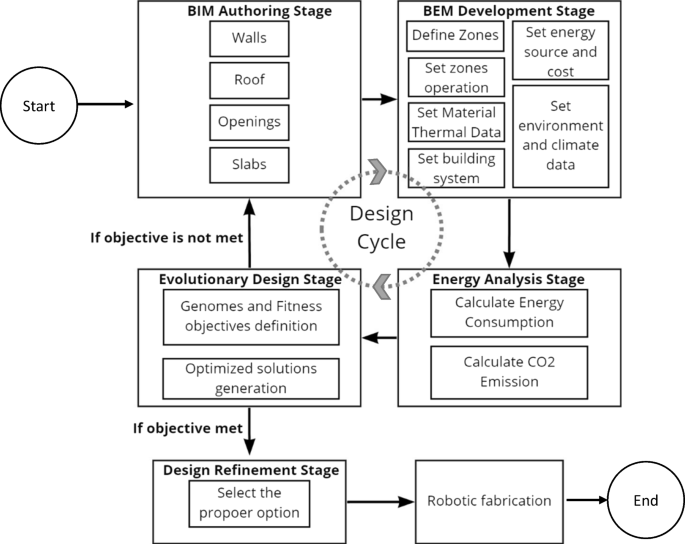
Figure 1 illustrates a comprehensive operational methodology designed to integrate Building BIM and robotic fabrication for the sustainable design and manufacturing of free-form building façade panels in off-site construction. The methodology is structured into five interconnected stages: BIM Authoring, BEM Development, Energy Analysis, Evolutionary Design, and Design Refinement, culminating in robotic fabrication. Each stage plays a crucial role in optimizing energy performance, minimizing material waste, and enhancing sustainability. The iterative design cycle ensures continuous improvement by refining the model until performance objectives are achieved. This approach leverages advanced digital tools and automated processes to deliver energy-efficient, high-quality building components, addressing modern construction challenges while adhering to sustainable development principles.
Proposed operational methodology
The process begins with the BIM Authoring Stage, where the foundational 3D model of the building is created. At this stage, essential elements such as walls, roof, openings, and slabs are defined and modeled. The BIM model serves as the digital blueprint for the project, ensuring all design details are captured accurately and prepared for further analysis. This detailed model forms the basis for integrating energy and performance data in subsequent stages.
Next, the BEM Development Stage transforms the BIM model into a Building Energy Model. This step is critical for simulating and analyzing the building’s energy performance. Several parameters are defined, starting with zoning, where the building is divided into functional areas based on usage. Each zone’s operation is configured to reflect realistic conditions such as occupancy schedules and equipment usage patterns. Material thermal data, including properties like insulation and conductivity, are assigned to ensure the model reflects the building’s thermal behavior. Building systems such as HVAC, lighting, and renewable energy sources are also defined. Additional inputs, including energy source and cost, as well as environmental and climate data (e.g., local weather conditions and solar radiation), complete the energy model. This comprehensive setup ensures accurate energy performance simulations.
With the BEM ready, the process advances to the Energy Analysis Stage, where the building’s energy performance and environmental impact are evaluated. Energy consumption is calculated for different scenarios to identify inefficiencies and opportunities for improvement. Simultaneously, carbon dioxide (CO2) emissions are estimated, enabling the project team to assess the building’s environmental footprint. The outcomes from this stage determine whether the design meets the desired sustainability objectives. If the objectives are not met, the process enters an iterative cycle for further refinement.
In the event the design requires optimization, the Evolutionary Design Stage comes into play. This stage employs advanced algorithms to refine the design. First, genomes representing design parameters are defined, alongside fitness objectives, which establish performance criteria for evaluation. Using evolutionary algorithms, multiple design iterations are generated, analyzed, and ranked based on their ability to meet sustainability goals. This iterative process allows the identification of optimized solutions that enhance energy efficiency and minimize environmental impact.
Once an optimal solution is identified, the process transitions to the Design Refinement Stage. Here, the best design option is selected based on its ability to meet predefined energy and sustainability objectives. This stage ensures that the finalized design balances performance, cost-effectiveness, and environmental considerations, making it ready for manufacturing.
The final step is Robotic Fabrication, where the optimized design is brought to life using robotic manufacturing techniques. The precise and automated nature of robotic fabrication ensures high-quality production of complex free-form façade panels, while reducing material waste and construction time. This stage integrates digital design directly with physical manufacturing, achieving a seamless transition from concept to construction.
The process incorporates a Design Cycle, allowing iterative improvements if objectives are not met at any stage. Feedback from energy analysis or optimization loops back to redefine and refine the model until the desired performance outcomes are achieved. This iterative approach ensures that the final product aligns with sustainability goals, making it a robust methodology for modern off-site construction.
Implementation and assessment
BEM development stage
In order to make a successful energy evaluation, the building model must contain at least the necessary elements such as the enveloping structures and fenestration, as well as all major internal structure which represent significant storage mass. A mock-up case study was simulated by using ArchiCAD 24 and Rhino 6.0. The building location was set to boulevard René-Lévesque Ouest, rue Guy, Montreal with coordination of 45.49, −73.57.
CADmapper was used to getting topography data and conceptual mass model of surrounding buildings. Once the conceptual building model is simulated by BIM tools such as ArchiCAD, in order to run the energy evaluation in BEM development stage and energy analysis stage, the following configurations are necessary:
Climate data
Defining the exact building geographical location will extract additional information about the condition of the site from online databases. Environment setting provides links to the Project Location, Data and Wind protection dialogs. Energy evaluation considers the geographic location of the building when obtaining climate data from the StruSoft Climate Server. StruSoft is an online database to provide required climate data based on the location of building in the period of one year for evaluation [37].
Soil type
Soil type can be set to the most closely option that describe the soil type of the building location. This setting will consider the basis for calculating heat flow through the building in contact with the ground. Each type contains relevant information for energy analysis includes thermal conductivity (W/mK), density (kg/m3) and heat capacity (J/kgK).
Surrounding and external shading
Surroundings configuration needs to be set to the best option that describes the closest environment of the building such as Waterfront, Garden and Paved. This setting will be used to calculate the effect of indirect solar irradiation in energy evaluation report. The proper wind protection levels for each orientation of the building must be set. By referring to the data obtained from CADmapper, the closet type which was partly protected was selected. Figure 2 shows the location and surrounding area of the case study.
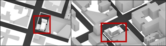
Location and surrounding area of the case study
Building system
Building systems of the model is categorized into four types: Heating, Cooling, Service hot-water generation and ventilation. There are three options to determine the closest building heating system: Natural heating, Local boiler and District heating. The natural heating is suitable for warm climate conditions that there is not large amount of energy required for heating, so the installation of a mechanical heating system is not necessary. However, this option is not implicated in Canada. The Local boiler or water heater is an option when there must be a local system supplies to the project. District heating means supplying an external plant in form of hot water through a pipeline. Natural, Mechanical and District cooling are available configuration for cooling systems. Natural system means cooling system involves no mechanical system; just natural air is used to cool the building. Mechanical cooling means that air conditioning system is applied to the building, it can be water-cooled or air-cooled system. District cooling is applied to some countries where conditioned air is obtained from an external source. For service hot-water generation, the desired temperature for cold water and hot water should be set either in degree Celsius or degree Fahrenheit. ArchiCAD EcoDesigner energy evaluation tool defines the default setting as 10 degrees Celsius for cold water and 60 degrees Celsius for hot water. The necessary amount of hot water per person is based on building function (l/day, capita). Natural, Exhaust-only and supply and exhaust systems are different types for ventilation system. The Natural ventilation means a system involves no mechanical equipment; only natural air movement is used for building ventilation and brings fresh air into the building. Exhaust-only system means using fans to extract used air from inside the building and brings fresh air into the building. Supply and exhaust system is the mechanical system which controls the exchange rate of air into the building. Therefore, the system can be programmed to have desired amount of air change per hour (ACH).
Thermal data
The usage of the building should be defined as its operation profile, it’s a predefined schedule based on occupancy type, by hour in duration of one year. The predefined schedules include required internal temperature, internal heat gain from humans, lighting and equipment, hot water needs and humidity need. Windows, doors that are known as opening of building as well as building material contains the relevant thermal data such as: U-value, infiltration rate, thermal mass, thermal conductivity, density, heat capacity and other factors which need to be defined to have adequate energy evaluation. Figure 3 shows a snapshot of the Building Energy Model consisting of all necessary configurations including building system, thermal data and each building zone operation hours as discussed above for the mock-up case study in this research.
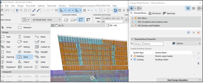
Snapshot of the building energy model
Energy analysis stage
As part of the research methodology, the energy performance evaluation report, shown in Fig. 4, represents the outcomes of the implementation and assessment stage, where the energy performance of the research case study is analyzed. This step aims to evaluate the building’s energy efficiency and environmental impact under real-world climatic and operational conditions. For the purpose of this research, Graphisoft ArchiCAD 24 used to prepare the energy performance evaluation report. Key data and parameters of the report are as follows:
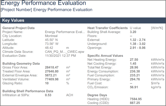
Energy evaluation report
General project data
The case study is situated in Montreal, with geographic and climatic inputs accurately reflecting the local conditions. The latitude, longitude, and climate file ensure the assessment considers seasonal heating and cooling requirements specific to this region.
Building geometry data
The large gross floor area (28,418.47 m2) and treated floor area (27,646.80 m2) underscore the project’s complexity, while the external envelope area and ventilated volume highlight key design parameters influencing energy performance. The glazing ratio of 10% represents a deliberate design choice to balance natural lighting and thermal insulation.
Building shell performance
The airtightness (0.53 ACH) indicates a high-performance envelope, effectively minimizing infiltration-related heat losses. This value plays a crucial role in maintaining the thermal efficiency of the building during cold winters and mild summers.
The energy evaluation report serves as a critical feedback mechanism in the research methodology. The results from the energy analysis step are used to identify performance gaps and refine the building design iteratively. For instance, the relatively high U-values for external walls and openings (1.32–8.06 W/m2K) suggest opportunities to enhance insulation and glazing systems to further reduce heating energy demand. The high energy consumption per square meter emphasizes the need for more efficient building systems or renewable energy integration. This stage aligns with the iterative design cycle illustrated in the methodology, ensuring that objectives are continuously reassessed until optimal solutions are achieved.
Evolutionary design
The next stage in the research methodology is Evolutionary Design, which aims to identify the optimum solution for the initial building design. This process leverages generative design tools and algorithms to refine the design iteratively, guided by predefined objectives. The methodology integrates several advanced tools to facilitate the evolutionary design process, with a focus on optimizing the façade design for energy efficiency and aesthetic performance.
Workflow integration: ArchiCAD and grasshopper
To begin the evolutionary design, the initial building model created in ArchiCAD 24 is connected to Rhino 6.0 using the Archicad-Grasshopper Live Connection plugin. This seamless integration ensures that the building’s geometric and parametric data are transferred accurately, enabling further design explorations in Rhino. Grasshopper acts as the primary platform for scripting and automating the generative design process, while Rhino provides a robust visualization and modeling environment.
Environmental analysis with ladybug
A critical component of the evolutionary design is understanding the site-specific environmental conditions, particularly the building’s exposure to solar radiation. Using Ladybug, a Grasshopper plugin for environmental analysis, the research team performed detailed simulations to evaluate radiation levels on the building’s façade throughout the year. This step is essential for identifying areas of high solar gain and understanding the relationship between the façade’s geometry and the environmental context.
Evolutionary algorithm and optimization with Wallacei
The generative design process is supported by Wallacei, a powerful evolutionary optimization engine within Grasshopper. Wallacei facilitates multi-objective optimization based on the defined design objectives and genomes (design variables).
Design Objectives: For this case study, the primary goals are:
- Minimizing solar radiation exposure: Reducing direct solar gain on the building’s façade to improve energy efficiency and reduce cooling loads.
- Minimizing the area of sunshades: Striking a balance between shading efficiency and material usage to optimize costs and maintain an elegant architectural appearance.
Genomes (Design Variables): The genomes are the parameters that influence the façade’s geometry, including the size, position, and orientation of shading devices, as well as the arrangement of glazing elements. These variables are adjusted iteratively during the optimization process to generate alternative designs.
Evolutionary design process
The evolutionary script combines the results of the environmental analysis with the design objectives to iteratively generate and evaluate design alternatives.
- Generation of Alternatives: Wallacei produces a population of design options, each representing a unique combination of façade elements.
- Evaluation of Fitness: Each design alternative is assessed based on its performance against the objectives. For example, designs with lower solar radiation exposure and smaller shading areas score higher in the fitness evaluation.
- Optimization: The evolutionary algorithm selects and combines the best-performing alternatives, refining the designs over multiple generations. This iterative process converges towards the optimal solution that balances energy efficiency, material usage, and architectural intent.
Selection of the optimum solution
The final output of the evolutionary design stage is a set of optimized façade designs that meet the research objectives. The selected solution achieves a balance between minimizing solar radiation exposure and optimizing shading device dimensions, ensuring energy efficiency without compromising the architectural quality. The optimized façade design is then passed to the subsequent stage for refinement and fabrication.
This evolutionary design process not only enhances the energy performance of the building but also demonstrates the potential of integrating computational tools like Grasshopper, Ladybug, and Wallacei into modular off-site construction workflows. It allows for data-driven decision-making and ensures that the selected design solutions align with the sustainability and performance goals of the project.
Discussion
The proposed operational methodology, as shown in Fig. 1, supports designers in developing Building Energy Models and implementing evolutionary design strategies to achieve optimal solutions. In this study, the methodology has been applied to the case study to derive an optimized façade design solution. The primary objectives are to minimize solar radiation on the building’s surfaces while reducing the total sunshade area.
Figure 5 illustrates the solar path analysis and radiation exposure for the selected site and building façade. This analysis enabled the calculation of solar radiation levels across all building façades, including the representative façade chosen for optimization. The radiation distribution on the façade exhibits significant variability, ranging from high exposure at the top-left corner to lower exposure towards the bottom-right corner. This variation necessitates tailored optimization for each panel of the façade to account for the distinct solar radiation levels across the building exterior. As a result, the design of each panel in the initial façade configuration must be uniquely adapted to achieve the most efficient solution.
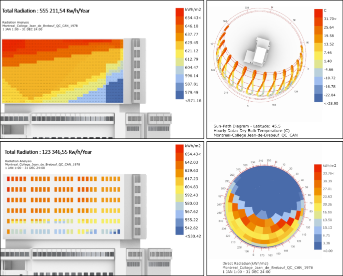
Analysis of the sun path of the selected site and illustration of the radiation exposure of the building facade of the case study
In Fig. 5, the left diagram shows the total annual radiation on the building’s façade in kilowatt-hours per square meter (kWh/m2). The color gradient represents the varying levels of solar exposure, ranging from high radiation (in red) to low radiation (in blue). The upper-left region of the façade experiences the highest radiation, exceeding 650 kWh/m2, due to direct and prolonged solar exposure. The sun path diagram provides a hemispherical view of the solar trajectory over the course of a year at the site’s latitude (45.5°N).
The circular grid indicates the sun’s position throughout the year, with warmer colors (red/orange) showing periods of higher solar intensity and cooler colors (blue) indicating lower intensity. The diagram also shows the dry-bulb temperature distribution alongside solar radiation, emphasizing the correlation between solar angles and thermal conditions. This information is crucial for understanding the seasonal and diurnal impact of solar radiation on the building façade. The lower-right region receives significantly less radiation, dropping below 580 kWh/m2, as it is more shaded. This variance highlights the uneven distribution of solar radiation across the façade. Therefore, the key observations from the radiation analysis are:
- Radiation Distribution: The façade experiences a gradient of solar radiation, with the top-left corner receiving maximum exposure and the bottom-right corner receiving the least.
- Design Implications: The variance in radiation necessitates a panel-specific optimization strategy to address the unique solar loads on different parts of the façade. This includes designing tailored sunshades or materials to reduce solar gain in high-exposure areas while maintaining energy efficiency.
- Seasonal Variation: The sun path and radiation diagrams highlight the importance of seasonal variations in solar exposure, which can inform dynamic shading solutions or adaptive façade systems.
By leveraging insights from the radiation analysis, multiple design alternatives for façade optimization can be generated. Figure 6 illustrates the evolutionary behavior of the design process, where alternatives are produced by varying the parameters of a defined genome represented by the OA vector.
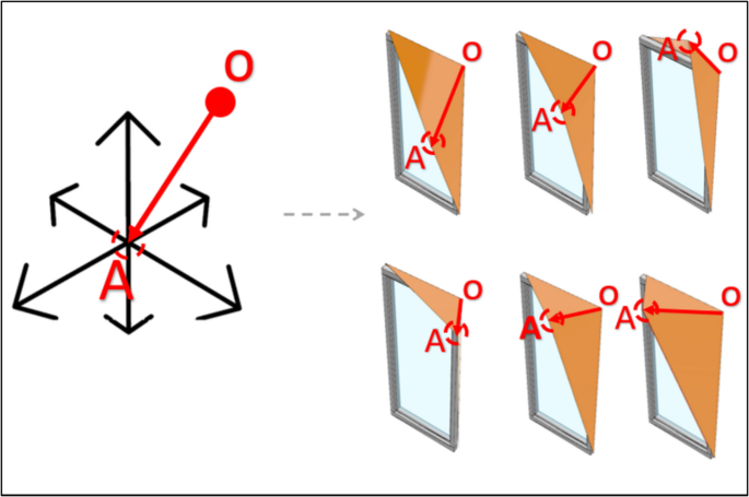
Behavior of the selected genomes for the evolutionary design performance
Main components in this process are as follows:
OA vector and genomic behavior
The OA vector originates at point O and extends to point A, defining the geometric configuration of the sunshade element for each façade panel. The movement of the OA vector along the XYZ axes acts as the parametric variable that generates various design options. By altering the position of node A, the shape and orientation of the sunshade adjust dynamically, creating alternative designs with different solar shading properties.
Parameter variance
The developed script allows controlled movement of the OA vector. This systematic manipulation generates numerous façade configurations tailored for solar radiation analysis. Each configuration maintains the functionality of sunshades while adjusting their geometry to optimize performance.
Tool implementation
Ladybug and Wallacei are employed for radiation analysis and evolutionary design processes. These tools enable an iterative approach to generating alternatives based on defined parameters and objectives. The genomes (parameter sets) are programmed to explore the design space, ensuring that the alternatives meet specific performance objectives.
Design objectives and fitness criteria
Fitness Objectives
FO1: Minimize the façade area dedicated to sunshades to reduce material usage and visual obstruction.
FO2: Minimize the solar radiation on the façade to enhance energy efficiency and thermal comfort.
Evolutionary analysis
By running the evolutionary algorithm, different façade configurations are generated that balance these two competing objectives. The analysis evaluates each alternative against the fitness objectives, identifying options that optimize both façade area and radiation exposure.
Figure 7 presents the comprehensive results from the Wallacei evolutionary solver, which was utilized to generate and evaluate various façade design alternatives based on the defined fitness objectives. The analysis highlights the radiation reduction and sunshade area optimization achieved through the evolutionary process.
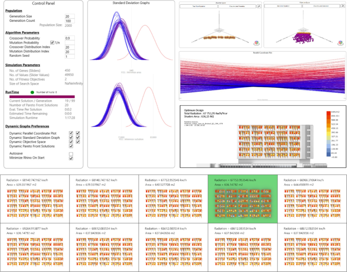
Summary of Wallacei results, new building facade radiation exposure analysis, and top 10 facade design results
This process is consisting of the following components:
Wallacei control panel
The control panel displays key parameters and settings for the simulation:
- Population Size: Set to 20, indicating the number of design alternatives generated per generation.
- Generation Count: A total of 100 generations were processed, resulting in 2,000 design iterations.
- Algorithm Parameters: These include crossover, mutation, and distribution probabilities, which govern the variability and exploration of the design space.
- Fitness Objectives (FO): FO1: Minimize façade area for sunshades, FO2: Minimize radiation exposure on the building façade.
Standard deviation graphs
These graphs depict the deviation of solutions within each generation:
- The narrower and sharper the deviation curve, the closer the solutions are to an optimal design.
- Over time, the curves converge, indicating that the algorithm has refined its search to achieve a balance between the two fitness objectives.
Dynamic graphs and plots
- Parallel Coordinate Plot: This plot visualizes the relationship between the fitness objectives and the genomes of each solution. The red and blue lines represent solutions with high and low fitness values, respectively.
- Objective Space: Displays the distribution of solutions relative to the two objectives, helping identify clusters of optimal solutions.
- Pareto Front Solutions: The most balanced solutions that meet both objectives effectively are highlighted here.
Top 10 solutions
The bottom section showcases the top 10 façade designs generated by the algorithm. These designs are ranked based on their performance in minimizing radiation and façade area. Each design indicates the total radiation in kWh/year and the corresponding sunshade area in square meters (m2). The chosen optimal design is highlighted with a green box.
Optimal solution
According to the analysis, the optimal design achieves a 45% reduction in radiation exposure compared to the baseline while maintaining a reasonably minimized sunshade area of 636.15 m2. This solution demonstrates a successful balance between the two fitness criteria, aligning with the project’s objectives.
Radiation analysis (Ladybug)
The radiation analysis results validate the effectiveness of the chosen design in reducing solar radiation on the building façade. The visualization further emphasizes the varying radiation levels across the façade and the significant improvement achieved through optimization.
Therefore, the Wallacei evolutionary solver effectively identifies high-performing design solutions by iteratively refining the population across generations. The parallel coordinate plot and dynamic graphs offer critical insights into the genome variations and the trade-offs between fitness objectives. The top 10 designs provide a range of viable options, ensuring flexibility for designers to select a solution that best fits their specific needs and priorities.
The chosen optimal design achieves a significant radiation reduction while maintaining a compact sunshade area, demonstrating the efficiency of the evolutionary design process.
The final stage is the robotic fabrication process. Figure 8 shows the snapshot of the output manufacturing simulation of the top section of the wooden sunshades. Each panel is uniquely designed to optimize the façade’s overall performance, balancing aesthetics, structural integrity, and environmental considerations. This process relies on digital fabrication techniques to enable accurate and rapid production. The process operates within a shared technological environment, ensuring seamless interoperability between design and manufacturing tools. This integration allows digital designs to be directly translated into physical components without compromise. To minimize material waste, the panels are strategically arranged on manufacturing boards using a nesting process. This arrangement optimizes the placement of the components to reduce excess material, ensuring sustainability and efficiency.
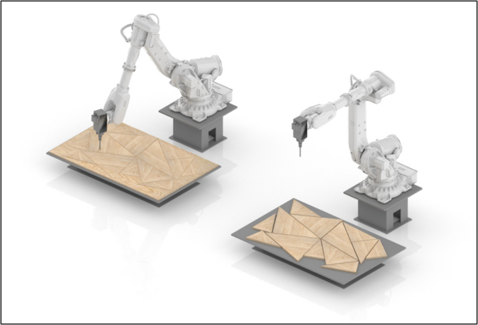
Snapshot of the output manufacturing simulation of the top section of the wooden sunshades
The edge geometry of each panel is extracted to define the robotic arm’s toolpath. Using inverse kinematics, the precise movements and positions of the robotic arm’s joints are calculated, enabling it to accurately follow the contours of each panel. The trajectory is then programmed using the Grasshopper Robots plugin, which simulates and generates the commands necessary for the CNC milling process. This approach allows for real-time simulation and control of the robotic arm, seamlessly integrating with BIM and computational design tools. Such integration ensures coordination between design and manufacturing, streamlining the production workflow.
Conclusion
The construction industry faces significant challenges in addressing inefficiencies, high energy consumption, and environmental impacts. This research proposes a comprehensive operational methodology that integrates BIM and robotic fabrication to enhance the design and execution of sustainable building façades in Off-site Construction Manufacturing. The challenges are particularly pronounced in the OSCM of free-form components like façade panels, which require substantial coordination, labor, and time due to their complex geometries and unique designs.
By leveraging generative design and evolutionary algorithms, the methodology optimizes façade designs to minimize solar radiation and material usage, thus improving energy efficiency and sustainability. The application of the proposed methodology to a mock-up case study demonstrated significant reductions in solar radiation exposure, validating its effectiveness in achieving sustainable design objectives. The integration with digital fabrication and robotic manufacturing ensures precision, reduces labor intensity, and expedites the construction process, addressing the inherent challenges of producing complex free-form components. This approach not only enhances the adaptability and efficiency of OSC workflows but also aligns with sustainable development principles.
The study identifies several limitations that warrant further exploration. One key limitation is the focus on façade components, suggesting that future research could extend the methodology to other building elements to enhance the overall construction process. Additionally, while the study integrates generative design and digital fabrication, there is a need to explore additional sustainability objectives and fitness criteria to fully realize the potential of the proposed methodology.
This study contributes a scalable framework for sustainable design and manufacturing in construction, with the potential to transform industry practices by bridging the gap between digital design and automated production.