Article Content
1 Introduction
Following the 2012 Rio + 20 Summit for Sustainable Development, where states committed to developing a suite of sustainable goals including waste reduction, the need for practical solutions has become increasingly urgent (UNSD, 2023). Governments and markets have been actively formulating regulations and legislation to address the challenges of low-carbon economies and resource depletion. In the built environment, research on waste reduction through reusing waste has gained significant traction, tackling diverse supply chains and waste types to offer tangible solutions to these pressing issues.
This project investigates the uses of offcut timber panels and is based on previous studies on the potential of upcycling Planar Quadrilateral (PQ) offcut timber panels to build a specific type of doubly-curved anticlastic geometry, the hyperbolic paraboloid (Hudert & Mangliár, 2023). In the past 12 years, researchers and practitioners in Architecture, Engineering and Construction have been investigating strategies to reduce the environmental impact of the building construction industry, and increasing the use of timber products has been one of the main ways to address this challenge. Recent studies on the replacement of concrete and steel structural systems with engineered timber products, such as Cross Laminated Timber (CLT), demonstrate that this approach is a viable and readily available solution to accelerate decarbonisation, along with designing more efficiently (D’Amico et al., 2021). However, several aspects must be considered, from exploring the shortest transport routes to carefully selecting only timber sourced from certified sustainable forest management. The debate around using timber as a substitute for carbon-intensive materials and the uncertain availability of timber has fostered discussions and research projects on the use of timber by-products. Studies on CLT production and surplus by Poteschkin et al. (2019) and methods and means to extend the service life of wooden components by Mangliár and Hudert (2022) have prompted investigations into new approaches to reclaiming scrap and waste wood as building components, highlighting that implementing the use of timber offcuts and waste in architecture is not only a matter of material performances; it is about design (Browne et al., 2022).
Offcuts from timber panel manufacturing, also defined as surplus or pre-consumer waste, are generally reprocessed – and therefore degraded – for the production of new particleboard; the environmental benefits of these processes are evident, but despite their odd shapes and small sizes, these offcuts are new and suitable for any of their initial intended purposes through a re-invention and rehabilitation, or upcycling, process to revalidate their value (Wegener, 2023). The term upcycling emerged from the work of McDonough and Braungart (2002) as opposed to a downcycling and downgrading process that generally requires energy and water to produce a material with less compelling properties than the original ones.
Upcycling discarded materials requires developing new skills and capabilities, instigating behavioural changes in how we buy, use, care for, and dispose of waste, and increasing awareness of circularity to better understand the interplay between theory and practice. It is commonly argued that the utilisation of offcut material is inherently beneficial as its use reduces environmental impact (McDonough & Braungart, 2002) but comes with a cost burden at various stages as (1) designing with non-standard materials might require adjustments, testing, and validation, (2) traditional manufacturing processes based on material characteristics that are nominally consistent throughout the supply chain may need modification to accommodate the variability introduced by the use of offcuts, and (3) the final user group may experience differences in product performance or aesthetics due to non-standard materials.
In this scenario, prototyping has proven necessary to develop new workflows and demonstrate the feasibility of these new processes to support practical implementation and facilitate knowledge exchange (Dokter et al., 2023). Many pavilions and installations from the past few years resulted from the experimentation with upcycling waste and surplus materials within and outside the construction industry. One of the first studies on upcycling reclaimed sports equipment for structural purposes, developed at the École Polytechnique Fédérale de Lausanne (EPFL) by Colabella et al. (2017), prompted the discussion about the value of cross-industry collaboration and was exhibited at the 2017 Biennale of Architecture in Lyon to demonstrate the necessity to reweight the value of time relative to the consumption of resources. The research by Robeller and Haaren (2020) includes a construction system for shell structures made from the door- and window cut-offs resulting from CLT production lines, showcasing via prototyping the general application possibilities and limitations of the proposed system. The two practice-based approaches by Browne et al. (2022) investigate the opportunities and challenges of using waste wood for basic architectural elements, such as walls and beams. “Offcut Tales” by Reisach (2023) is an experimental installation where discarded offcuts from timber manufacturers are revealed to celebrate the imperfections of these scavenged timber pieces as natural aesthetic qualities.
The use of waste has informed and inspired many artistic installations such as “Symbiosen” (2023), a temporary parasitic space built by Raumlabor and local participants for the Fragile Festival at the Pina Bausch Zentrum in Wuppertal, Germany. This installation was made of a discarded shipping container previously used for transporting stage design, old furniture and discarded wood. The bottom-up approach to reuse and co-design is essential in creating a broader network that is ready to promote circular thinking and has the potential to enable the government to facilitate the transition to environmental system changes, as envisioned by Meath et al. (2023) and Dokter et al. (2023).
Our research aim is to contribute to both aspects of behavioural change towards waste and innovative ways to reduce wood production waste via upcycling as an alternative resource in building construction. It does so by testing and analysing a prototype made of surplus timber panels, specifically, Laminated Veneer Lumber (LVL) offcuts donated by Tilling Timber. The prototypical pavilion called Hypar Up has been designed and built to test the feasibility of a design-to-fabrication workflow based on a process that enables small and planar timber offcuts to approximate complex but modular geometries via a PQ mesh (Fig. 1). The construction of this pavilion was achieved through a collaboration between a design team based at Aarhus University and a fabrication team at The University of Melbourne. The structure was built for the 2023 design competition of the International Association for Shell and Spatial Structures (IASS) at the annual symposium of the association held in Melbourne. The design competition was organised by the IASS Working Group 21, focusing on “Advanced manufacturing and materials”, and required all participants to design and build a structure that displays a strong vision of structural design and innovation, particularly in production techniques, materiality, constructability, transportability and architectural expression.
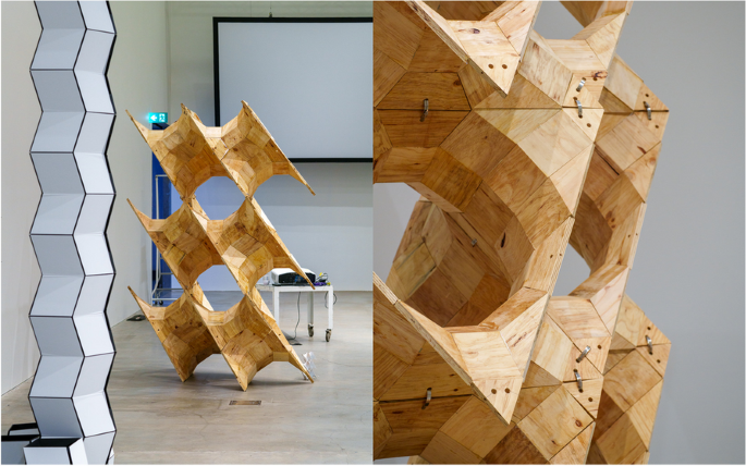
The Hypar Up pavilion exhibited at the RMIT Design Hub for the IASS 2023 Design Competition (Photos by James Rafferty, 13 July 2023)
Since this research aims to demonstrate the feasibility of an integrated approach that blends computational design and optimisation with effective manufacturing processes, leading to efficient and innovative uses of surplus timber products, we focused on two research questions:
- Q1: How can small-sized planar surplus timber products be repurposed in modular and geometrically efficient ways to design and manufacture complex architectural and building components?
- Q2: How can we evaluate the efficiency and feasibility of design-to-manufacturing workflows with small-sized planar surplus timber products?
The premise of Q1 is that there are still no convenient pathways for valuable surplus timber offcuts to get re-circulated in the building industry, especially when they are small-sized. This problem is due to the unavoidable risk of designing with materials with uncertain characteristics, such as surplus and offcuts, and the consequent necessity to increase dimensional design tolerances.
To answer Q1, we used the pavilion design submitted for the 2023 IASS design competition as the case study, in which the overall geometry and structural topology were fixed parameters while the cross-sectional dimensions were variable. To answer Q2, we developed a quantitative analysis of costs and labour involved in developing the Hypar Up prototype to evaluate the manufacturing process. The method for this analysis involved recording the resources employed for the production of the pavilion from industrial timber offcuts to develop a cost analysis of the manufacturing process and a subsequent cost model as a theoretical pricing model broadly representative of the real-world conditions of a manufacturing enterprise.
The methodology involves empirical methods and pursues a research-by-design approach, including prototyping testing and comparative analysis. The design and construction of a modular structure informed an iterative development process, leading to refinements and improvements and a comparative study with other methods to evaluate the effectiveness of the workflow.
The paper is structured as follows:
- Section 2 explains why the hyperbolic paraboloid has been selected as the base geometry for this research work. It discusses building applications and uses for this structural form and describes the challenges of building anticlastic doubly-curved shapes through small planar elements, and a process of geometry discretisation into PQ meshes.
- Section 3 illustrates the design of our Hypar Up pavilion, from the definition of its basic hyperbolic paraboloid module to the final assembly of six modules made of PQ offcut tiles.
- Section 4 discusses the fabrication of the pavilion for the 2023 IASS design competition.
- Section 5 analyses the costs associated with our design-to-construction workflow, discussing the overall feasibility of this design-to-fabrication process in a real-world scenario.
- Section 6 summarises how we answered the research questions in Sections 4 and 5 and discusses an alternative workflow that should be explored in future studies.
2 Design and construction with the hyperbolic paraboloid
The hyperbolic paraboloid – often shortened to hypar or HP surface – is a translational surface mathematically described by translating one planar parabola along a second orthogonal parabola of opposite curvature (Sandaker et al., 2019). This operation results in a doubly curved surface with negative Gaussian curvature.
The hypar has been widely used as a basic geometry in architecture and structural design because it can also be generated as a ruled surface by moving a straight line (Pottman et al., 2008). This property simplifies the preparation of building components and concrete falseworks from planar elements and makes the geometry of hypars easy to draw and deal with at the conceptual design stages. Since parabolic curves are good approximations of catenary shapes, hypars are inherently structurally efficient and suitable for large-span roofing systems and lightweight building components.
Ruled surface structures, including those based on hypars, can be built from either similar or identical discrete elements. This characteristic can contribute to the reusability of the parts employed (Hudert, 2021) and offers an opportunity for designing modular hyperbolic paraboloid units made of prefabricated timber components.
2.1 Notable examples
With the rapid advancements in parametric modelling software and analysis tools, the problems associated with describing, rationalising and optimising complex geometries in architectural and structural design have become increasingly more significant and have revamped architectural geometry as a research field. Architectural Geometry by Helmut Pottman et al. (2008) is arguably the most comprehensive book on the topic and the richest collection of architectural projects in which geometry played a key role in the architectural design process to define rational and cost-effective solutions. However, placing geometry at the core of a performance-oriented design process is not a new concept, and the real precursors of this approach can be found in the early 19th century when descriptive geometry was established as a discipline for civil and military engineers because of the post-revolution reorganisation of teaching in France. Gaspard Monge and his students Sylvestre-François Lacroix and Jean-Nicolas Pierre Hachette are considered key protagonists of this change and authors of reference books on the subject matter (Barbin, 2019).
Although there is no direct evidence to demonstrate Antoni Gaudí’s engagement with treatises on descriptive geometry, such as Hachette’s book (1822), it is also no coincidence that the Sagrada Familia, originally designed using a reverse hanging model, was then built by rationalising its parts with geometric forms, particularly ruled surfaces like the hyperbolic paraboloid and the hyperboloid (Burry, 2011).
Gómez-Serrano et al. (1997) argue that Gaudí began developing an architecture based on ruled-surface geometries during the last years of his career, between 1914 and 1926. In their paper, the researchers illustrate how complex the composition and intersection of hypars and hyperboloids are in Gaudí’s Sagrada Familia and how useful this approach to design through geometry is nowadays for completing the church construction (Gómez-Serrano et al., 2009).
In the second postwar period, several architects and structural engineers began developing a passion for lightweight structures, particularly reinforced concrete shells. It was still a period in which designers could not rely on digital 3D modelling and FEM analysis software, and the main way to design and build performative and cost-effective concrete structures was through the understanding of geometry. Cylinders and other ruled surfaces, including hyperbolic paraboloids, were frequently used to design shell roofing systems, and textbooks of statics and descriptive geometry came back as sources of inspiration for the design of lightweight structures that combine excellent mechanical behaviour with ease of construction.
To mention one of the many local examples, Italian architect Pino Pizzigoni began studying hyperbolic paraboloids in the late 50 s by reading Aimond’s books on thin shells and hypar geometries (Aimond, 1933, 1936). From that period onwards, he regularly used hypars in his projects, starting from his most known and successful design: the Church of Longuelo (Deregibus & Pugnale, 2010). This church is a unique example that combines a concrete space frame with 20 hypar structures stacked on each other, and the Philips Pavilion, designed through the collaboration between Le Corbusier and Iannis Xenakis for the 1958 Brussels World’s Fair, can be considered its direct antecedent, at least in terms of structural typology. Regarding formal complexity and articulation of hypar shells to define shelter, space and voids, the Philip Pavilion does not come close to the qualities of Pizzigoni’s church.
Alongside Gaudí’s Sagrada Familia, this church design is a testament to the architectural quality achievable when basic and simple geometries are coherently trimmed, intersected and articulated to design sequences of structures and spaces.
Félix Candela is regarded as the master builder of hypar-shaped thin shells (Garlock & Billington, 2008). The reasons why he used hypar geometries so extensively are clear. To use his own words, Candela said that “of all the shapes we can give to the shell, the easiest and most practical to build is the hyperbolic paraboloid”, and that the hypar “is the only warped surface whose equation is simple enough to permit stress calculation by elementary mathematics” (Candela, 1963).
In his career, Candela explored various ways of trimming, intersecting and articulating hypar modules to design large-span structures. These projects can be clustered into two main families: those based on hypars trimmed with vertical planes, therefore featuring straight edges, and those cut with inclined planes, defining curved edges. Candela’s most complex composition of hypars with straight edges is visible in the 1955 project for the Iglesia de la Medalla Milagrosa, whereas his most known project featuring curved-edge hypars is the 1958 Los Manantiales restaurant.
The use of ruled surfaces and hyperbolic paraboloids in architectural design does not end with the thin shells of the second postwar period. We can see these geometries in several large-span roofing systems of the past few decades, even though current applications favour discrete elements rather than concrete. Similarly to Gaudí’s Escuelas de la Sagrada Familia (1909) and completed in 2001, the Bodegas Ysios Winery by Santiago Calatrava features a wavy conoid roof that emphasises the generative process of its geometry through the use of discrete timber beams (Barrallo & Sánchez-Beitia, 2011). The Hypar Pavilion, designed by Diller Scofidio + Renfro in collaboration with FXCollaborative, and the Antwerp Law Courts, designed by Richard Roger Partnership in association with VK Studio, are both recent projects engineered by ARUP that use hypar geometries as the main design feature.
2.2 Discretisation of doubly-curved surfaces with PQ meshes
The design and construction of doubly-curved shell structures made of discrete flat elements is a topic that has been investigated since the early 90 s, with the pioneering research by Schlaich and Schober (1994) on strategies to translate and scale curves to generate doubly-curved PQ meshes for glass gridshells. Exemplar glass gridshells designed from PQ meshes include the courtyard roof at the Museum for Hamburg History, completed in 1989, and the structure for the House for Hippopotamus at the Berlin Zoo, built in 1996. Glymph et al. (2004) expand on Schlaich’s and Schober’s work by implementing translation surfaces generating PQ meshes into CATIA, a computational parametric software. In 2015, Schober closed the loop by publishing Transparent Shells, a book on gridshell design that includes a comprehensive chapter on methods to discretise a broad range of surfaces into PQ meshes. This chapter approaches the discretisation of the hypar in two ways: as a translation surface and as a ruled surface (Schober, 2015).
Optimisation-based approaches to discretise free forms into PQ meshes also began to appear at the beginning of this century. For example, Sassone and Pugnale (2010) illustrate how to transform free-form NURBS surfaces into PQ meshes through two separate methods: a relaxation algorithm and a Genetic Algorithm, each of which has pros and cons in terms of efficiency and the level of approximation of the generated outputs. More recently, Mesnil et al. (2016) developed a new parametric method to design PQ meshes inspired by descriptive geometry. This method offers a broader design space than the geometrically constrained approaches discussed above and works with open and closed surfaces. The introduction of singular points is necessary for approximating complex geometries. Jiang et al. (2021) proposed discretising a surface into PQ meshes by exploiting the geometry of the two diagonal meshes of a control mesh. This method gives the designer good control over node angles and the individual quad faces.
Thanks to innovative digital workflows and assembly techniques, timber-based panels for segmented timber shells have been widely experimented with, demonstrating that designing and building appealing architectures with timber is both feasible and necessary (Menges et al., 2016). A significant number of timber pavilions have been designed and built at the University of Stuttgart by the Institute for Computational Design (ICD) and the Institute of Building Structures and Structural Design (ITKE) to test innovative computer-controlled manufacturing methods, e.g., ICD/ITKE Research Pavilion 2011 and Urbach Tower 2019, robotic manufacturing for automated assembly and milling, e.g., BUGA Wood Pavilion 2019, celebrating pioneering paradigm shift in timber design and manufacturing (Aldinger et al., 2020; Bechert et al., 2021 and Wagner et al., 2020). At the IBOIS Laboratory for Timber Constructions, EPFL, Switzerland, digital design and fabrication of CLT folded surface structures have been investigated since 2005 (Buri & Weinand, 2006), showing the potential to design large-scale free-form structures from small timber plates. More recent studies have focused on the experimentation and enhancement of 5-axis CNC-fabricated joints suitable for irregularly shaped segmented shells (Robeller & Haaren, 2020). A key aspect of these research projects is the creation of computational tools that allow the generation and verification of the overall geometry and geometry code (G-Code) required to fabricate the single plates (Robeller & Weinand, 2015). The robotic assembly of non-standard optimised timber structures research field, initiated by the group of Gramazio Kohler Research at ETH Zurich in 2005, has long been focusing on the design implications of bespoke robotic fabrication processes (Gramazio et al., 2014) that allow complex joinery for complex designs. A step further in the fabrication process optimisation is the “Additive Robotic Fabrication of Complex Timber Structures” research project, where higher degrees of geometric freedom are achieved by simplifying the production of timber components (Kohlhammer et al., 2017).
Our research builds on this extensive literature and illustrates an application and potential implementation strategies for salvaging, repurposing, and incorporating offcuts in new products, whose structural performance is harnessed through geometry and redundancy, as suggested by Block (2022). Given the usual small dimensions of timber panel offcuts, the experimentation with PQ meshes seemed an obvious choice.
3 Pavilion design
As discussed in the introduction, the Hypar Up pavilion was designed to investigate the potential of upcycling timber panel offcuts into modular construction components based on hypar geometry.
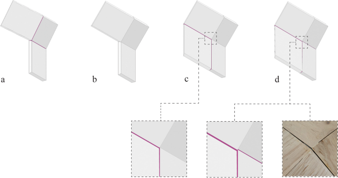
The geometric property of hyperbolic paraboloids allowed the discretisation of the Hypar Up pavilion into PQ elements, permitting small offcut panels to be used. This property is described by Schober (2015): “flat quads can be created by connecting the corresponding points of intersection of the generatrixes in diagonal direction”. Although he described this geometric property of hypars in the context of using glass panels as cladding elements for steel/glass gridshells, this characteristic is also relevant to the design and fabrication of segmented timber shell components. By introducing a virtual grid, diagonally aligned with the hypar rulings, it is possible to create a PQ mesh that can be fabricated from planar wooden pieces (Fig. 2).
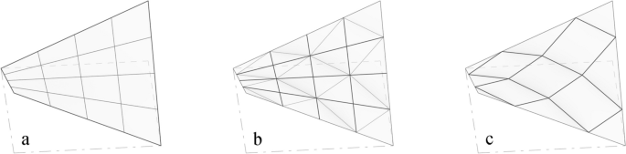
Discretisation of a hypar into a PQ mesh: a hypar surface subdivision based on the ruling lines; b connecting the intersection points to generate a new grid in the diagonal direction; c the new grid of PQ panels. (Drawings based on Hudert & Mangliár, 2023)
The range of possible ways to stack and articulate such hypar modules into different multi-hypar structures mainly depends on the geometry of the basic unit. Hudert and Mangliár (2023) focused on two ways to stack hypar modules to design open and closed configurations (Fig. 3).
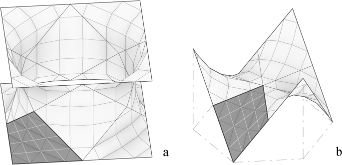
Patches of an approximated Schwarz P surface: a closed Schwarz P surface condition with twelve patches; b an open configuration with six patches. (Drawings based on Hudert & Mangliár, 2023)
The closed variation illustrated in Fig. 3a approximates a Schwarz P minimal surface when the module is replicated twelve times. The same hypar module is also used in some of Ángel Duarte’s sculptures and in projects he developed in collaboration with Heinz Isler (Chilton, 2000; Ramm & Schunck, 2002; Ludwig, 2021).
The second variation was used for the design of the Hypar Up pavilion. If we inscribe this hypar module into a cube, its boundary edges correspond to the diagonals of the cube faces. Combining a minimum of four of these modules can generate higher-order star-shaped geometries. The Hypar Up pavilion, assembled from six of these units, represents one of the many possible configurations of this particular modular system (Fig. 4). It also displays properties similar to those of triply periodic surfaces, as illustrated in Fig. 4a, and its appearance smoothly transitions between open and closed when moving around it.
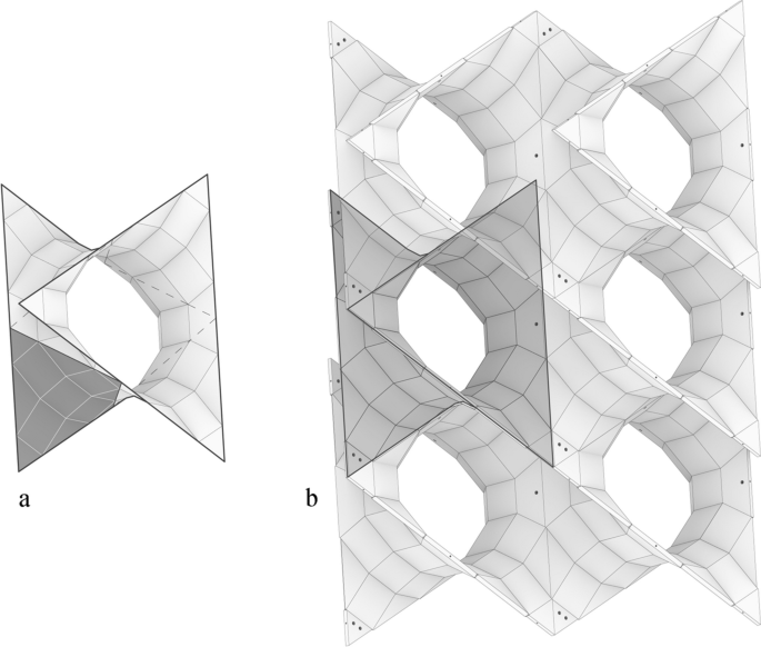
The Hypar Up pavilion: a Star-shaped hypar module obtained by combining six identical hypar geometries; b the pavilion design, combining six star-shaped modules. (Drawings based on Hudert & Mangliár, 2023)
Preliminary studies for the Hypar Up pavilion were carried out as part of the MSc course “Tectonics in Engineering and Architectural Design” at Aarhus University. In the fall semester of 2020, students were asked to develop reusable and reconfigurable timber construction systems based on ruled surfaces capable of serving as charging stations for electric vehicles (Hudert, 2021). Ángel Duarte’s work was presented to the students as an antecedent for designing modular hypar structures. In the fall semester of 2021, the focus was on combinatorial design strategies for hypar modules. In the first part of the course, students were introduced to WASP, a Grasshopper plugin for Rhinoceros 3D developed by Andrea Rossi. Students investigated possible aggregation processes and connections by using WASP, and it is worth noting that the combination of six hypar modules into star-shaped units was first observed in the student work from this course. However, similar and preceding studies that feature the combination of this hypar geometry into larger structures can also be seen in Michael Burt’s work (Burt & Korren, 1996).
One of the primary objectives of this research is to develop a reconfigurable and reusable timber construction system based on timber production waste (Fig. 5). The Hypar Up pavilion serves as a tangible example of how six segmented hypar modules can be integrated into a higher-order unit to form a wall-like structure (Fig. 4b). Within these higher-order units, triangular mesh faces on the boundary of adjacent hypars can be merged into larger flat meshes. The high degree of symmetry in the overall structure enables the construction of the entire pavilion using only six distinct panel types, underlining the practicality and efficiency of the system.
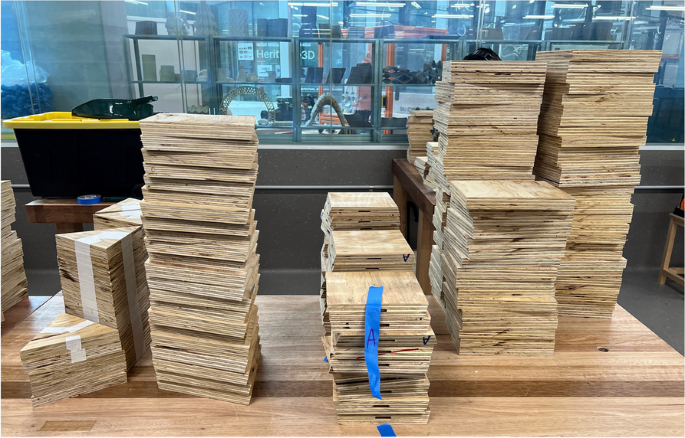
The base panels used to build Hypar Up in Melbourne (Photo by Sofia Colabella, 4 July 2023)
The initial idea was to build the Hypar Up pavilion from scrap wood; therefore, the size of the pavilion and mesh faces was conceived to allow construction using timber production offcuts. Translating meshes with zero thickness into volumetric geometries for fabrication with wooden panels can raise several challenges. Issues are minimal with conical meshes because their offset results in planar edge and mesh faces in equal distance, as all quads adjacent to one vertex are tangent to a common cone. With hypar-shaped meshes that are not conical, this offset method produces flawed results. One possible solution is to adjust the mesh so that it becomes conical. Alternatively, it is possible to chamfer the corners of the offset quads, as shown in Stotz et al. (2009). A third approach is to describe the geometry of the panels as convex polyhedrons, defined by the intersecting half-spaces of their six boundary planes. This strategy generates parallel yet slightly misaligned edges for neighbouring panels, but the edge surfaces are planar. We chose this latter geometrical conversion from surface to volume to simplify the production and experimentation with widely available tools in the construction industry, available in many architecture schools, such as a table saw and a 3-axis CNC milling machine.
4 Design-to-fabrication workflow
The Hypar Up pavilion was designed as a reconfigurable modular hypar system that could be made of standard 18 mm plywood offcuts. It followed a digital design-to-fabrication logic using CAD/CAM processes to translate any adjustments made to the design parameters in immediate updates to the manufacturing outputs. Given its parametric logic, the initial assumption was that specific variables – mainly relative to the material provided – could be easily adjusted while maintaining the overall design intention. As per the schematic design instructions by Hudert and Mangliár (2023), the design team originally conceived hypar-shaped construction components to be fabricated as six three-dimensional modular units from planar base material for 2700 mm height. Each unit has an edge length of 1200 mm and comprises 60 base panels, classified into four main types: triangular, rectangular, rhombic, and trapezoid. The anticipated thickness of the panels was 18 mm, and their edge lengths ranged from 160 to 300 mm. All panel-to-panel connections were originally supposed to allow glue-less assembly and disassembly through conventional dowels (Fig. 6).
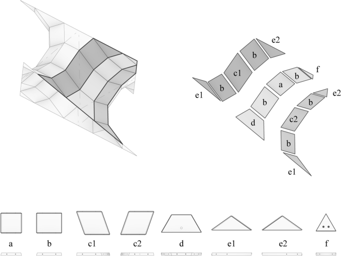
A higher-order unit and its composition. (Fabrication logic: Markus Hudert and László Mangliár. Modelling and image editing: Michael Minghi Park)
As the panels donated by Tilling Timber Pty Ltd as offcuts of one of their production lines (38 sheets of 7 layers, 21 mm LVL in 2400 × 300 mm, 2 cross-branded veneers) were thicker than the designed ones, the original detailed drawings based on 18 mm birch plywood could not be directly converted into ready-to-manufacture shop drawings, given the non-orthogonal connections between the panels. Therefore, adjustments had to be rapidly made to account for the 3 mm increase in material thickness while revising the fabrication timeline to fit the 2023 IASS design competition deadline.
LVL is a high-strength engineered timber manufactured by bonding rotary-peeled thin wood veneers along the grain direction under heat and pressure. LVL veneers can be peeled from very small logs, making them highly efficient from a production point of view (Kamke, 2004). Given its overall performance, salvaging LVL offcuts can be very convenient if matched with an efficient workflow.
LVL shrinks and swells in proportion to changes in moisture content between 0 and 28% fibre saturation point. However, while a final thickness variation along the length of 3–4 mm in a large piece of LVL can be accounted for when detailing, the seamless connections between the small-sized quads were inextricably linked to the Hypar Up aesthetics, and any imperfections and misalignment of its unconcealed joints would have compromised the final result. We initially hypothesised to optimise the proposed design for 5- or 6-axis machining to allow precision of +/- 0.1 mm of the edge connections and minimise tolerances. We rapidly discarded this solution due to time constraints and machine availability in the Faculty of Architecture, Building and Planning (ABP) Maker Spaces, and optimised the design of the pavilion parts for hybrid manual woodworking (conventional table saw with additional jigs constructed for distinct parts) and a 3-axis CNC router.
4.1 Test prototype
The fabrication process started with prototyping a mock-up of one higher-order hypar unit to test optimal time, material and equipment parameters. We fabricated the higher-order unit prototype with readily available 18 mm CD structural plywood sheets while waiting for the delivery of the LVL offcuts to be used for the pavilion. Through this initial prototyping test, we identified inconsistency in material thickness and human error as the most significant sources of deviation. These issues prompted several changes, including halving the number of connection points, substituting the dowel pins with domino connections (Fig. 7), and engraving visual markers onto the base panels to assist alignment. Additionally, we prepared jigs for table saw, vertical drill press, and lamination and assembly. Implementing these changes increased the efficiency and accuracy of the full fabrication and assembly.
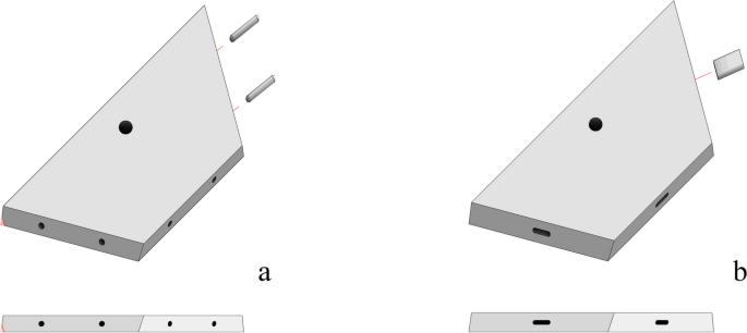
Base panels: a with dowel pins; b with domino connections
We segmented the prototyping process into three phases, each testing different fabrication and assembly stages. Phase 1 concerned the production of 60 base panels from a single sheet of 18 mm non-structural plywood. Phase 2 focused on assembling the base panels into strips, while Phase 3 involved assembling the strips into higher-order units. We monitored the efficiency and accuracy of the making process during each stage, and we tested and implemented alternative solutions when proven more effective. Upon completion of Phase 3, we could test the feasibility and stability of a complete higher-order unit.
We fabricated the 60 base panels with a 3-axis CNC machine to reduce the fabrication time (Fig. 8). However, the machining constraints of the 3-axis CNC router prompted significant changes to the fabrication workflow. We had to restrict all edges to a 90-degree angle, requiring additional processing with a table saw (Fig. 9). We could not fabricate the horizontal pockets and had to go through extra processing with the drill press (Fig. 10). Given the many machines necessary for the fabrication of the base panels, we planned to fabricate the actual components of the final pavilion with a combination of the table saw and drop saw for the initial profiling of base panels discarding the 3-axis CNC machine. While this change significantly increased time efficiency, it also elevated human errors.
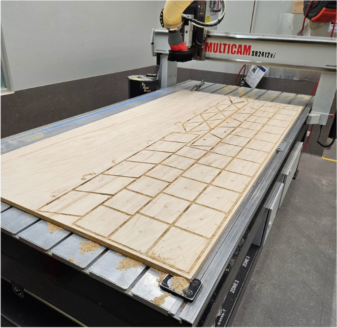
The 3-axis CNC machine used for producing the test base panels with readily available 18 mm CD structural plywood sheets while waiting for the delivery of the LVL offcuts (Photo by Michael Minghi Park, 23 June 2023)
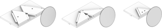
Table saw jigs for base-panel type D, E and F
Drill press jig for base-panel type F
We designed the machining jigs to account for non-parallel profile angles, maximise fabrication efficiency, and allow for scaling. The elements labelled A, B, and C did not require additional jigs since they were parallelograms. We produced three unique table saw jigs for the 120-, 35.3-, and 60-degree profile angles of the base panels type D, E, and F, respectively. We rotated the blade on the table saw to produce the 9.7-, 17.6-, and 15-degree edge angles. We made an additional drill press jig to process the horizontal pocket of base-panel type F (Fig. 10). Once tested, the machining jigs could be scaled up to account for the 3 mm increase in thickness.
During Phase 2, we assembled the 60 base panels into 12 strips. Each high-order unit comprises 6 type-A, 3 type-B and 3 type-C strips (Fig. 11). Each strip comprises 5 base panels connected at non-perpendicular joint angles. Due to the non-perpendicular joint angles and the compounding human error from Phase 1, we provided all joints with significant tolerances, and we produced a set of jigs for the lamination and assembly. Given the symmetrical nature of joint angles for type-B and type-C strips, only two sets of formwork sections, S1 and S2 (Figs. 11 and 12), were necessary to assemble one high-order unit, each comprising 128 joints.
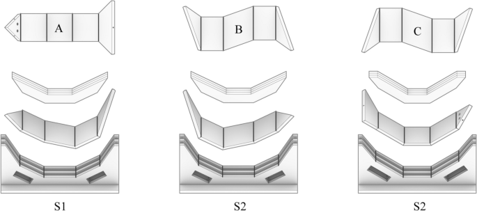
Strip and formwork drawings. (Fabrication logic: Markus Hudert and László Mangliár. Modelling and image editing: Michael Minghi Park)
The strips and the formworks (Photo by Sofia Colabella, 6 July 2023)
Due to the complexity of the joints and the compounding human error in Phase 1, we substituted the dowel connections with floating tenons, thus halving the number of connection points and increasing the tolerance for each connection. A single 6 by 30 by 20 mm pocket was cut on each joint face using a DF 500 Domino Joining Machine. Each pocket was cut at the centre of and normal to the joint face. The cutting angle was adjusted to the 9.7-, 15-, and 17.6-degree angles of the joint faces using the angle adjustment pivot of the domino joining machine.
We produced six sets of S1 and S2 formwork sections for the lamination and assembly of the 12 strips. The 12 formwork sections were fabricated from 4 sheets of 18 mm CD structural plywood (face veneer quality of C grade and back veneer quality of D grade) using the 3-axis CNC router. The use of the 3-axis CNC router maximised the time efficiency and minimised the error.
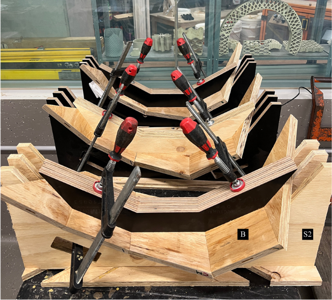
Despite the initial intention to avoid glued connections, the joints of the strip assemblies could not hold their configuration, relying solely on the floating tenons; therefore, a thin film of water-based wood glue, requiring 20–30 min of clamp time and 24 h to cure was included in the fabrication of the strips. We profiled the vertical components of the jigs to facilitate the specific angles of the strips and cut a series of pockets to position the clamps throughout the curing. We designed the horizontal components of the jigs to secure the vertical components in a parallel and equidistant arrangement.
Phase 2 highlighted critical bottlenecks in the manufacturing process impacting the production schedule. A key issue was the limited availability of the 3-axis CNC router, restricting the number of lamination jigs that could be produced within the project timeframe and, consequently, the higher-order units that could be processed simultaneously. The mitigation strategy to prioritise the fabrication of the initial 120 base panels required for 2 high-order units ensured that their assembly could proceed without waiting for additional base panels to be produced, thus reducing the overall lead time.
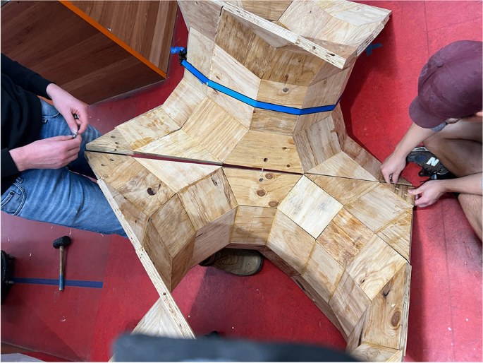
During phase 3, 12 strips were assembled into 1 higher-order unit. An initial step of dry assembly where strips were friction-fitted with domino tenons and supported with masking tape (Fig. 13) allowed the fabrication team to identify difficulties in the assembly before the strips were fully laminated. Given the geometric complexity of the higher-order unit, it was more practical and efficient to laminate without using jigs. Instead, the higher-order unit was assembled by 2 workers compressing the units together. This analogue method proved successful and informed the use of ratchet straps and tensioning rope for the final fabrication and assembly (Fig. 14).
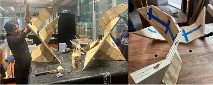
Dry assembly of a modular unit (Photo a by Alberto Pugnale; b by Michael Minghi Park, 8 July 2023)
The assembled prototype module at the ABP Maker Spaces (Photo by Sofia Colabella, 9 July 2023)
4.2 Final prototype
The prototyping test allowed critical adjustments relative to the fabrication process and its schedule to meet the 2023 IASS design competition deadline. The 21 mm LVL offcut panels used for the fabrication of the pavilion were derived from a single production line; therefore, their thickness and stress grade were consistent. Generally, in large LVL panels, thickness tolerance variation depends on the shrinking and swelling of the panel in proportion to changes in moisture content. However, while a final thickness variation of 3–4 mm along the length in a large piece of LVL can be accounted for when detailing, the Hypar Up design was based on seamless connections between the small-sized quads, and any imperfections and misalignment of the unconcealed joints would have compromised the pavilion aesthetic and the fitness of the unit edges.
As anticipated with the test prototype, the final pavilion showed a significant accumulation of tolerances: the sum of each small panel variation led to large variations of the strips, which prevented the use of flush-edge connectors. In response, we employed stainless steel hose clamps as an alternative method of assembling the higher-order units (Fig. 15). This simple joint design allowed a straightforward assembly and disassembly process of the six units in less than 3 h. While the prefabrication of the modules allowed a fast and almost effortless assembly at the exhibition venue, their size and volume determined a sub-optimal shipment, as outlined in Section 5. The two parameters of storage and shipment did not need to be optimised for the competition, but both could have been implemented by preassembling only two halves of each higher-order unit, allowing the 12 halves to be shipped in one round instead of three. We did not adopt this solution as it could have created a crease along the connection, potentially compromising the structural performance of each unit, extra labour at the exhibition location, and additional design time and tests of the dry connection between the two halves.
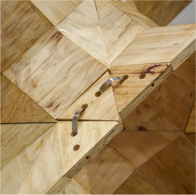
Detail of the edge connector (Photo by James Rafferty, 14 July 2023)
5 Efficiency study
As Bernard Cache observed in his Philibert de l’Orme Pavilion (Cache, 2003), reality is made of approximations and probabilities, in contrast with the exact precision of the digital realm of software operating with codes and algorithms. This contrast reveals itself in almost every attempt to transform a digitally designed product into a physical one. This observation applies to our case, as we had to find design solutions accounting for gaps and inaccuracies in the production and assembly of the Hypar Up pavilion. Fundamental to these challenges is the problem of compounding errors in edge and fixing placement tolerance for each module. Inconsistencies emerged through the deployment of a labour force with varied levels of training, experience, and natural aptitude or human error, in combination with the use of the domino joining method. The tool used to cut the mortise, as relates to the tenon, on any given edge is adjusted by eye – and by trial and error – to achieve a nominal mortise at the centre of the part edge, further compounded by the need for varied edge/face angles across parts.
As shown in Figs. 16, 17 and 18, the inherent inaccuracy of the manual angle cutting and domino fitting processes contributed to the misalignments in the overall assembly of each module. This incongruency is an inherent risk to any design that aspires to mitred connection details in the pursuit of surface continuity and reveals a minimal joining logic of the components.
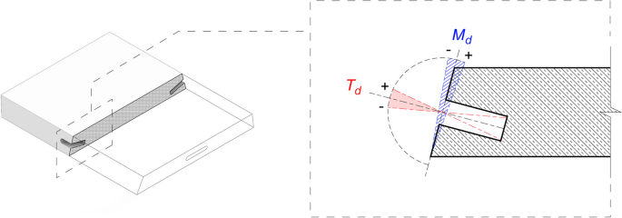
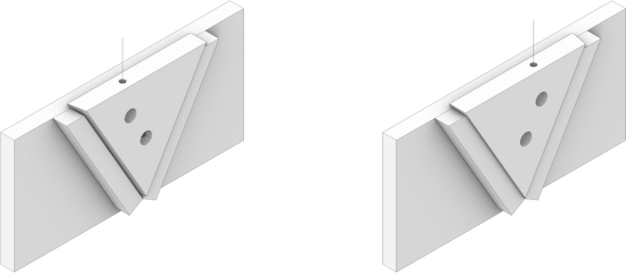
Possible deviation in tolerance in mitre joint machining
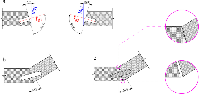
Hypothetical deviation in mitre joint: a for a 30-degree target angle; b when the domino tenon is excluded; c when the domino tenon is included
Mitre deviation across PQ mesh connections: a mitre joints sitting at their intended angles, with gaps shown in pink; b mitre joints sitting at incorrect angles, adjusted to close gaps; c inserting a fourth panel creates new gaps; d attempt to correct, which translates inaccuracy across joints creating more gaps
Combining two imperfect fabrication processes creates the potential for a compounding incongruency between joining faces. In other words, deviation from the specific mitre angle to be achieved is possible in two instances: the cutting of the joining face edge and the setting of the domino mortice at the normal of that same face. This effect is compounded further when we consider that each face and each mortise of any joining instance are created in separate machining operations, effectively making the possibility of error fourfold.
This error can be approximated by calculating both the deviation in the mitred – joining face – angle and the separate deviation – if any – of the domino to the normal of its corresponding face. Figure 16 denotes the achieved angle of the mitre (inclined plane), Md. The achieved angle of insertion of the domino is denoted by Td and is calculated relative to the normal of the perpendicular intersecting plane. As any joint requires two component edges, the mitre angle of deviation is denoted by Md, whilst the angle of deviation of the domino – mortise and tenon – is denoted by Td, where the numbers correspond to the index of the face.
This method approximates the overall deviation in a joint instance by combining all four opportunities for deviation to occur. However, in practice, errors can interact in more complex ways, and the actual deviation could be different because of the combined incongruency, which would include a function in any instance where the tenon deviation (Td) is not equal to 0 degrees. This problem occurs because the tenon deviation (Td1 + Td2) supersedes the mitre deviation (Md1 + Md2) during assembly, as shown in Fig. 17, where nominal deviations are simulated in all four instances. Figure 17a shows a hypothetical joint when the target angle is 30 degrees, but the machining is inaccurate; Fig. 17b illustrates the resulting angle and inaccuracy when the domino tenon is excluded; Fig. 17c shows the angle of the mortice when the domino tenon is included, superseding the angle of the mitre creating inaccuracies in the joint. This issue results in both an undesirable angle and a poorly fitting joint.
When considering the overall effect of deviation across a series of joining instances, an exact outcome requires indexing the unique deviation at each instance. While it is possible that an equal deviation in the negative could offset a deviation in the positive, this is unlikely to happen without intention and control during fabrication to ensure consistency and accuracy.
As the pavilion module is a PQ mesh, the impacts of incorrect joining instances are compounded in multiple axes. Single joining instances – per axis – occur with deviation with resultant gaps shown in pink (Fig. 18a). These joins are allowed to sit at their incorrect angles, thus appearing closed and intentional (Fig. 18b). However, when an adjoining diagonal panel is affixed, the compound errors occurring in both initial axes of assembly are immediately present (Fig. 18c). Reducing the deviation, presented as a gap in the mitred joint, requires compensation in adjacent joint instances, creating more openings (Fig. 18d). The combination of PQ mesh and mitre joining techniques means that inaccuracy is always translated between joints and cannot be corrected.
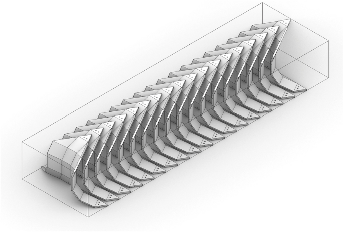
A further challenge to the efficiency of the manufacturing process is the inverse duality between the efficiency of the installation through the six units and the inherent inefficiency of their transportation. By conducting a basic analysis of part volume against bounding volume (Table 1), we can determine simple principles as to the inefficiency of the demonstrated transportation method against a more efficient method wherein the level of discretisation of components during transport is set against other key factors including stock holding and implied costs of on-site assembly. This analysis does not pre-suppose vehicle parameters; instead, it focuses on the general packability of various geometry. It is worth noting that this exercise does not account for supports or protective packing to each component, and further efficiency may be found when using 3D packing algorithms.
Figure 19 illustrates Method A1, which involves transporting the fully assembled modules with the open face planar with the ground. Method A1 is the simplest yet most inefficient method, with a yield of only 3.52% of total transport volume, calculated as the volume of the bounding box of the method. Figure 20 represents Method A2, which produces a marginal efficiency gain by orienting the module to its assembled position relative to other neighbouring modules, with yield increasing slightly to 4.34%.
Method A1: Module packing example
Method A2: Module packing example
The highest-order assembly, which improves packing, occurs when the module is broken into thirds, as shown in Table 1, corresponding to a module factor of 0.33. We define the module factor as the level of assembly the components have achieved at the time of transportation. A factor of 1 means the modules are fully assembled, whereas a factor of 0.33 indicates the modules are being transported in thirds.
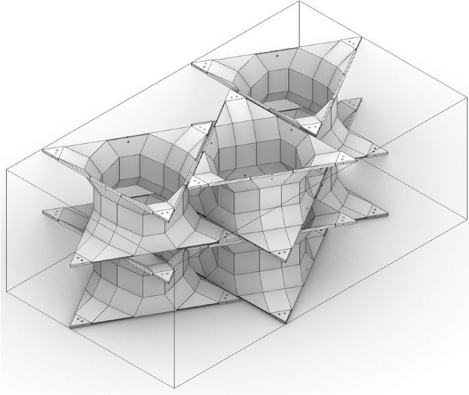
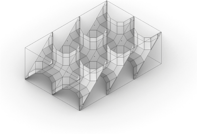
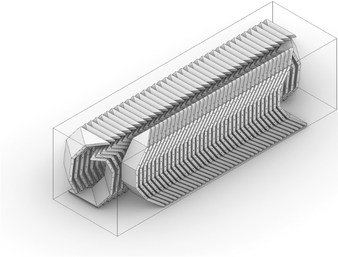
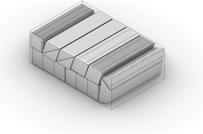
Figure 21 illustrates Method B, which reduces but does not eliminate the double curvature of the module, allowing for an ‘offset surface’ nesting logic. Meaningful efficiency gains only appear when the module is broken down into sub-assemblies as in Method C (Fig. 22). These sub-assemblies align with the demonstrated fabrication of the pavilion prototype, consisting of assembled strips (Fig. 12). By nesting these strips, the hypar surface is deconstructed to a singular curvature per unit, creating a marked improvement in nesting efficiency and a transportation yield of 32% of total packing volume while simultaneously maintaining the benefit of prefabrication workflows.
Method B: Doubly curved 1/3 packing example
Method C: Strip sub-assembly packing example
The next step, falling outside of the assembly process optimisation, is considering the packability of discrete components. Using Method D (Fig. 23), no assembly would occur in the factory; instead, all joining operations would rely on prescriptive assembly instructions, the nature of the joining device – hardware or integral – and manual labour on-site. At this level of component resolution, packability can be optimised to include the nesting of elements by mirroring their non-orthogonal edges and angles, achieving a yield of 54.1%. Despite this higher yield, we can see from Table 1 that this method requires all joints to be assembled on-site and could undermine the advantages of prefabrication.
Method D: Components packing example
If we consider Method C the most viable solution, further improvements are possible when scaling beyond our 6-module prototype and considering larger design applications. As in Method C2 (Fig. 24), increasing the number of modules to 60 and nominally compartmentalising specific geometry sets into discrete nests or shipments increases the yield to 40.22% of the total shipment volume. Despite this improvement, such a low yield might still be conceived as unacceptable.
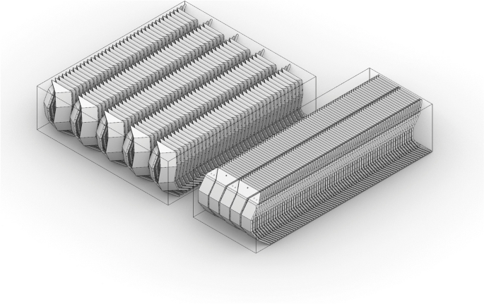
Method C2: 60-module sub-assembly-like-parts packing example
In the context of the pavilion competition, a core parameter was that the structure could be packed and transported using six suitcases and assembled in 1 day, which is only applicable to method B, as it allows an optimal packing volume while permitting the minimum prefabrication to assemble the prototype within the timeframe. This rule required us to differentiate between the intent of prefabrication for the competition and prefabrication for potential application in the industry.
To further understand the feasibility of the design as an architectural product, we can use data collected from the fabrication of the Hypar Up pavilion (Table 2).
Table 2 describes the calculation for the total labour hours to prototype and fabricate Hypar Up, which was 246.25 h. Workshop staff, across a range of roles, accounted for 218.25 h, with academic volunteer helpers making up the remainder.
As the material was donated post-industrial waste, material costs were minimal, considering consumables such as dominos (tenons) and adhesive, as well as materials purchased for the initial prototyping tests that were ultimately not used in the final design (Tables 3 and 4). The final cost category of machine depreciation considers the value of the machine over time and its expected duration of use and utilisation over that time to account for the cost of owning and operating the required machines (Table 5). We calculated the depreciation values by referring to the methodology used by the Australian Taxation Office (ATO) to determine the effective life of depreciating assets under section 40–100 of the Income Tax Assessment Act 1997. Given the University’s general ability to procure equipment outright, the interest on loan is not included.
6 Cost model
Modelling a hypothetical transition of the Hypar Up prototyping process to a commercial production involved a shift from the isolated data points collected during the manufacturing stage to a holistic view of costs and revenue to verify what adjustments would be necessary if the product and the process could align with business goals of a hypothetical real-world enterprise.
To assess and contextualise the economic viability of our pavilion as an architectural product, we used data collected through the prototyping process, such as labour hours, material use, and machine selection relative to fabrication methodology, to inform a commercial fabrication cost model that extends beyond the prototyping stage. This cost model (Tables 6, 7, 8 and 9), expressed in Australian dollars (AUD), excludes a range of capital, administrative, legal, operational, and taxation expenses not apparent within the prototyping phase. Nevertheless, contextualising available data within a model commercial reality provides a hypothetical costing scenario that helps better understand a project overall commercial viability.
This model utilises data applicable to Australia, including industry roles, pay rates and interest costs, but does not include all overheads such as utilities and property costs or insurance, etc. However, it may be broadly applicable to other markets by simply adjusting these jurisdictionally specific parameters. It should be noted that all businesses are unique and have specific costs which affect their ability to price work. Therefore, this model aims to represent a generic business within the market, specifically that generic business model for pricing a complex architectural product using both surplus non-standard stock and standard stock. Labour cost savings by using standard inputs are contingent on processes. Where CAD programmes with tools for automated nesting functions are used, the labour impact of using non-standard inputs is greatly reduced. This fact is contingent on the inputs being of the same general quality of material, with the ‘non-standard’ stock – i.e., offcuts – being only dimensionally distinct from the ‘standard’ or new stock.
The fabrication enterprise is provided with the same design development information as the fabrication team in the Hypar Up prototyping project undertaken at The University of Melbourne:
- General Arrangement of the components to be fabricated.
- 3D data, including individual parts and assembled components.
- A general fabrication methodology envisioned by the designer.
- Specification of raw materials to be used.
The total cost model assumes an equivalent scale of work to the Hypar Up prototype, with a per-module price extracted to demonstrate the design scalability.
The prospective inefficiencies of manually responsive nesting can be overcome with current CAD/CAM tools and nesting algorithms. These tools often carry their cost implications but are becoming more accessible in the digitisation of manufacturing. One market solution, Autodesk Fusion360, provides 2D nesting functionality as a plugin feature. Applied to one Hypar Up component, this tool allows for near-instantaneous recalculation of job parameters, including the re-generation of CAM tool-pathing.
While the above cost model excludes costs related to workshop space due to the high level of variability, considered use of space for prefabrication workflows is essential. The storage costs associated with lean manufacturing are always intended to be low. However, the arrival time of prefabricated modules to the site is dictated by a range of factors, including the capacity for the site to hold components and the requirements of their installation (Yi et al., 2019).
In analysing the transport methodology above, packing method C (Fig. 22) was considered to achieve the most efficient ratio of part yield per m3 packed to joint instances on site. This method radically reduced site labour impact at the cost of a relatively inefficient packing yield.
Packing method D (Fig. 23), where all sub-assembly components are manufactured but not assembled, is the best-case scenario for manufacturer stock holding if the Hypar Up module is considered a standard architectural product. This method allows the manufacturer to hold stock at the most efficient packing yield and, within an arranged lead time, complete partial assembly to the desired resolution for shipping. The requirement for long holding capacity is 0.35 m3, and short-term holding capacity – the duration of lead time – of 2.43 m3 for an outcome equivalent to the Hypar Up.
7 Conclusions and discussion
Prototyping the Hypar Up with LVL offcuts highlighted the necessity for reflecting on the disciplinary and interdisciplinary knowledge underpinning ecological design thinking and exploring the production process and its outcome. Within this context, the investigation extended to the relationship between design and craft, e.g. how materials and tools can be a limiting factor during fabrication. While the necessity for a more equitable and sustainable use of global resources through upcycling surplus construction materials is not disputable, we still need to optimise the marginal effects of such practical implementation. As expected, the traditional design-to-fabrication process was altered in many ways because of the use of offcuts of unknown sizes. This issue is common when building with non-commercial products and properties; therefore, accepting the challenge of designing with surplus and waste requires a flexible design approach that can adapt to uncertainties linked to the materials employed.
The manufacturing and installation of the Hypar Up pavilion emphasised the logic and the contradictions between the design intent – facilitated by the deterministic nature of digital design tools – and the actual execution – governed by the inherent variability of reclaimed materials that requires constant recalibration of the process, frequent measurements, and problem-solving skills. The correlation between anticipated and actual fabrication is crucial to any fabrication process planning. However, this issue becomes more relevant when introducing the uncertainties of unknown characteristics and properties of surplus materials. The interplay between the precision of the digital domain and the imperfection of using offcuts highlighted a tension between budget, time constraints and material limitations, raising the need to optimise the manufacturing process.
This nonlinear transition from design intent to execution shows that, in the pursuit of a circular economy within the architecture and construction industries, there is an opportunity for a shift in design thinking that challenges conventional design and construction practices. Such a shift is a necessary and strategic step towards bridging the significant gap in the research on this topic, which can be achieved by creating new frameworks to upskill both architects and construction companies. This process involves a multifaceted approach focusing on both technical knowledge and collaborative practices but also requires taking advantage of architectural geometry as the primary source of knowledge for rationalising complex forms at both the design and construction stages.
By approaching sustainable design through continuous learning, technical proficiency, creative design informed by material and structural efficiency, and early collaboration with stakeholders and industry partners, this study has offered an application and evaluative perspective on the repurposing of surplus materials that take advantage of widely available fabrication machines and tools in the construction industry. The workflow presented in this paper allowed for the design and construction of a 2800 mm x 1800 mm x 900 mm pavilion based on the prefabrication of six higher-order units bounded in a 900 mm3 box. The pavilion is intended as a 1:1 modular prototype that can be resized to accommodate different dimensions of the timber panel offcuts: each unit can be assembled using the same workflow and smaller panels, composing a smaller unit suitable for the construction of load-bearing walls and façade design. Since it is modular, the system allows for stack, end-to-end and side-by-side configurations. Potential applications of this system to be further developed in the future include thermal and acoustic retrofitting of existing facades by focusing on the vertical connections to existing structures and loadbearing walls by focusing on the connections to horizontal structures and envelope systems. Further studies should focus on developing these details, including corner solutions, connection to the ground and the roof, and verification of their suitability to diverse architectural and performance requirements. This future research will include structural analysis and comparison with traditional façade systems.
Inherent to the optimisation of the fabrication process and the reusability of the Hypar Up components are the adjustments to the design input for cost management and testing with 5- and 6-axis robotic milling to optimise the tolerances in edge connections and minimise human error. Robotic precision could lead to joint designs that do not require glue, increasing assembly and disassembly speed and simplifying any future reuses of the panels. A different pathway to overcome dimensional tolerances and multi-angular joint instances includes hybrid fabrication methods with additive manufacturing, which, as tested by Lee et al. (2024), could allow all edges to be cut at 90 degrees, thus reducing the complexity of machining, assembly, and transportation costs based on a flat-pack model. While this solution would benefit the timber fabrication machining efficiencies, it may add complexity to the joint fabrication and require further cost and life cycle analysis. Given the cost investment of machining and labour time (Table 6), the assembly costs are expected to be optimised by employing timber robotic fabrication. Further studies and prototypes would be necessary to construct a cost comparison to enrich research in this field.
Although many parts of the system need further development to be applied in the building industry and for future research with timber panels, this research approach can be considered a driver to upscale the early adoption of salvaged materials that can ultimately divert surplus materials from landfills and contribute to the necessary systematic and seismic change for achieving circularity by 2030, encouraging and spreading knowledge and practices of circularity to shift the way investors and stakeholders perceive the use of scraps in the building industry.