Article Content
1 Introduction
Rocket thrust is generated by converting the internal chemical energy within fuel molecules into the flow’s kinetic energy, so Newton’s third law concept can be applied as shown in Equation 1. A combustion chamber is responsible for converting the internal energy into thermal energy, delivering a high temperature and pressured fluid. Nozzles were invented to alter flow properties (velocity, pressure, and temperature) through compression and expansion. When the flow must be expanded from stagnation conditions to supersonic, a de Laval nozzle can be used. An initial convergent section will accelerate the flow subsonically. If the operating pressure ratio between the chamber and the ambient is high enough, the flow will choke at the section with the smallest transversal area, reaching a sonic value. This smallest transversal section is called the throat, and since it has a fixed Mach number, its dimensions, combined with chamber conditions, define the nozzle’s mass flow rate. Downstream of the throat, the flow will expand supersonically, needing area increases to do so. This divergent section, and its design, will have tremendous implications on the flow leaving the nozzle and generating thrust, so it is the major design focus as it defines the efficiency of converting thermal energy into usable kinetic energy. The most pertinent performance parameters of a nozzle are the specific impulse, in Equation 2, that represents the thrust generated by the weight flow rate of propellant consumed and the thrust coefficient, in Equation 3, representing the dimensionless value of thrust obtained relating to the chamber pressure and the throat area [1].
Nozzles are designed so they expand the flow with minimal losses. Conventional nozzles are already very effective, with less than 15% isentropic losses, but usually struggle when operating out of the design altitude [2].
For higher altitudes, and a higher pressure ratio between chamber and ambient, the flow will keep expanding past the exit section of the nozzle, not fully converting all thermal energy into kinetic energy, representing losses in comparison with an ideal case. Some losses can be attributed to the non axiality of the flow at the exit plane. A relevant characteristic of the underexpanded flowfield is a Mach disk, that forms as the flow at the centerline keeps expanding within the exhaust plume, until a strong shock is needed to raise the pressure so it matches ambient one. Flow can keep expanding and then compressing, creating a Mach diamond structure downstream. Some empiric models were built to predict the diameter and localization of such Mach disk. Although the exclusivity is not consensual, it is accepted that the Mach disk moves downstream with decreasing ambient pressure with an also increasing diameter, which can be manipulated using secondary flows [3]. Cumber [4] found the previous diameter correlation deteriorates for higher pressure ratios, attributing the fact to turbulent effects, which are dependent upon the nozzle geometry of both the divergent and the convergent sections [5].
At low pressure ratios near the ground, ambient pressure exceeds exit pressure, causing a Mach disk-shaped shock to form, which raises the pressure and permits a free boundary. In this overexpanding scenarios, the flow will most likely not use the full divergent section, having a separation point. For a free shock separation (FSS) some back flow may enter the nozzle degrading performance but with little safety hazards. When the Mach disk is inside the nozzle, it can tilt, redirecting the flow to the nozzle wall, causing reattachment, trapping an unstable separation bubble, representing a restricted shock separation (RSS). The transition between FSS and RSS is asymmetrical, with a similarly asymmetrical separation point moving toward the exit, creating drastic side-loads, representing the major concern during startup and overexpanding operation of ascending rockets [6].
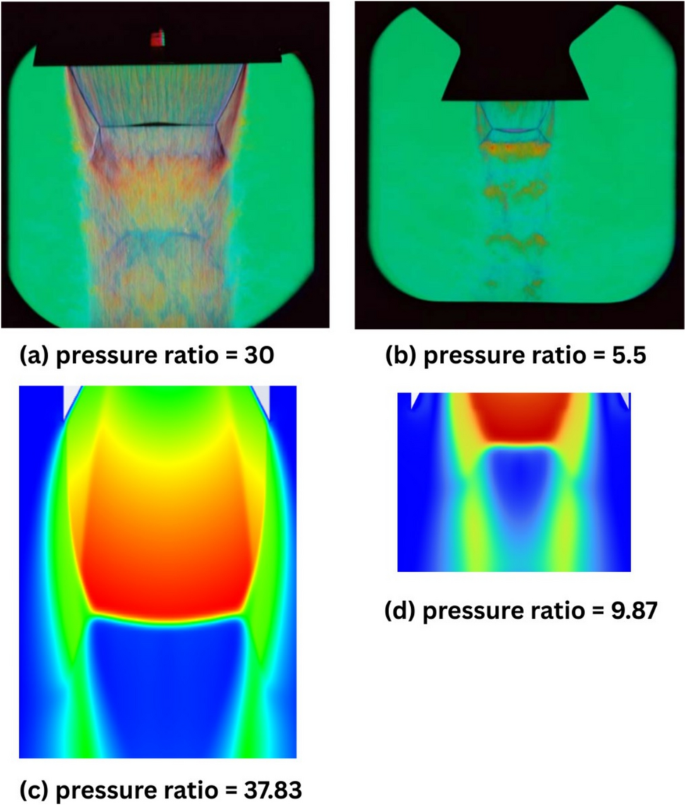
1.2 Cone nozzle
Cone nozzles, the simplest divergent contour, are characterized by the half-angle α, which balances nozzle length and flow divergence angle at the exit. A half-angle of 15° typically offers the best compromise. This type of nozzle is very susceptible to flow separation at overexpansion operation. In practice, cone nozzles do not exhibit an isentropic solution, even when functioning at design conditions. This results from two key factors. First, as the flow expands along the conical surface, it moves inward, inevitably generating a shock at the exit plane. Second, the throat geometry is too sharp, even with small half-cone angles, leading to the consistent formation of an oblique shock within the nozzle. Experimentally, this produces a characteristic double Mach diamond pattern, with its thickness reaching a maximum near design conditions and a small Mach disk forming inside the nozzle. This is visualized in Figure 1 where it must be highlighted that even at design operation, a Mach disk is found inside the nozzle. Shadowgraph images demonstrate that underexpanded flow conditions enhance expansion at the throat, sometimes disrupting the Mach diamond structure. As the exit Mach number increases, the Mach diamond cells become more elongated, with the two shocks merging after the first set of compression and expansion waves. In overexpanded cases, a reduction in Mach number also leads to the merging of the Mach diamonds, primarily due to the formation of a Mach disk induced by the lip shock, with a diameter approximately half of the exit [7]. Like in other traditional nozzles during overexpansion, the entire contour is not fully utilized, leading to separation at the end. This scenario poses risks due to the generation of side loads, especially during start-up [7] and reattachment during the transition to total contour utilization. To mitigate the throat shock and achieve an isentropic cone nozzle, the suggestion of incorporating an initial expanding arc has been made. Yet, utilizing the axisymmetrical Method of Characteristics shows that a weak oblique shock will always originate from the point where the arc meets the cone, unless the junction is carefully designed to minimize or nearly eliminate the shock’s visibility [8]. For missile applications, where easy fabrication and low area-ratio are design requirements, cone nozzles represent a good trade-off [9].
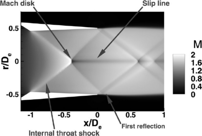
CFD visualization of flow behavior within a cone nozzle at design conditions [7]
When the operation of planar cone nozzles is analyzed with more complex CFD tools, losses can be lower than those expected with isentropic analyses where all the flow is assumed to exit with the same angle of the nozzle’s cone. In fact, an optimistic prediction is maximum for α = 20º and minimum for higher values (30º and 40º). This difference decreases moving from the design pressure ratio, being neglectful for highly underexpanded nozzles. As expected thrust reduces with the half angle increases, specially in design and underexpanded operation, as in overexpanding conditions, angles of 10º and 20º are more efficient. It has also been proven, thrust and efficiency are also affected by the convergent due to turbulent effects, mainly due to the wall shear stress, sensible to geometry [10].
1.3 Bell nozzle
Bell nozzles are contoured divergent section consisting of an initial arc-circle (expanding section) with high divergence angles of up to 50º, with little isentropic losses due to the high pressure gradient right downstream of the throat. The angle is than reduced axiality (straightening section) until meeting the exit value, assumed at design. Angle transitions must be smooth and inflections points avoided as irregularities in the contour can impart isentropic losses on the flow through shocks. A totally axial exit flow is possible, but the divergent section of the nozzle will be long, which is not practical for rocket propulsion, but desired for supersonic wind tunnel applications. So, a tradeoff between exit angle and nozzle length must be considered. The most common exit angles for bell nozzles range from 8º to 11.5º. Both cases represent a compromise between flow divergence and nozzle length [11]. The higher the exit angle, the more downstream will the first oblique shock be, facilitating the attaining of a truly shock free flow within the nozzle [12].
1.3.1 Thrust optimized parabolic nozzle
Rao [13] proposed a method to obtain the most efficient nozzle contour for a prescribed length and area ratio. The approach primarily focused on identifying the initial arc-circle that would enable optimal expansion by utilizing the Method of Characteristics. This was achieved by maximizing the integral function representing thrust, while adhering to specific constraints, through the application of the Lagrangian multiplier method. The nozzle contour was then determined by following mass conservation along the characteristic lines in the straightening section. Later, it was found that this process could be simplified by tracing a parabolic shape with minimal thrust losses. As a result, parabolic nozzles are commonly referred to as having thrust optimized parabolic (TOP) contours.
1.3.2 Truncated ideal compressed nozzle
The truncated ideal compressed (TIC) nozzle, often compared to the TOP nozzle, is derived from an ideal contour. As the name suggests, it is truncated at the exit area required for the design exit Mach number and then compressed to the desired length.
1.3.3 TOP versus TIC
Hoffman [14] utilized the Method of Characteristics to compare the performance of TIC and TOP nozzles. The study revealed that for all cases, TOP nozzles outperform TIC nozzles, but by a low margin ranging from 0.04% to 0.34%. This indicates that TIC contours are a viable alternative when TOP nozzles are not suitable. It was also observed that longer initial ideal nozzles, with a higher area ratio, tend to remain shock-free when truncated and compressed. This is because the truncation almost leaves them with the desired length, leading to less compression.
According to the literature, the major difference between TOP and TIC nozzles arises from transient effects of the transition between RSS and FSS overexpanding modes. While investigating TIC contoured bell nozzles, Takahashi [15] linked the transition between FSS and RSS to the interaction between the separation point and the Mach disk. Furthermore, in TIC nozzles, there’s an abrupt fall of pressure after the initial expansion followed by a slight increase. This changes the wall pressure, moving the separation point and causing it to interact with the Mach disk, leading to RSS, with considerable side-loads. Stark [16] experimentally studied both TIC and TOP nozzles to further understand the phenomena mentioned earlier, especially why the flow was being redirected to the wall, generating a RSS. For nozzles operating at higher pressure ratios, discontinuities in wall pressure were found but attributed to nitrogen condensation, highlighting a key phenomenon in real flow. CFD and experimental studies showed that the Mach disk was either convex or concave, but the convexity did not explain the RSS mode for overexpanding nozzles at low pressure ratios and did not seem to affect the intensity of side-loads. In some experimental trials, the RSS mode was observable for a pressure ratio of 5. The mechanism behind the transition was the separation shock that disturbed the Mach disk, tilting it and causing the flow to be redirected to the contour wall, leading to reattachment of the flow. Bakulu [17] further explored the mechanisms behind the FSS to RSS transition. Acoustic studies suggested that transonic resonance may be present near the axis, between the Mach disk and the exit, for a TIC nozzle, generating a standing pressure wave downstream of the separation shock, capable of moving the separation point. Although the exact physical mechanism could not be explained, for a TIC nozzle, this transonic resonance can be responsible for up to 20% of the side loads generated during start-up due to the transition from FSS to RSS. A faster transition from RSS back to FSS, which can reduce the duration of side loads to neglectful acceleration upon the vehicle, can be achieved with secondary gas injection after the separation point, increasing wall pressure near the end of the contour [18].
1.4 Contemporary rocket nozzle research
Conventional bell-type nozzles, despite their widespread use, are fundamentally limited by their fixed geometry, which is optimized for a single altitude. As a rocket ascends, atmospheric pressure drops, and the mismatch between nozzle exit pressure and ambient pressure leads to performance losses, up to 15% in some scenarios. Overexpansion at low altitudes can cause flow separation and dangerous side-loads, while underexpansion at high altitudes results in inef- ficient thrust. These limitations make bell nozzles less suitable for missions requiring optimal performance across a wide range of altitudes.
Advanced rocket nozzle designs improve engine performance by adapting to changing ambient pressures during ascent, minimizing energy losses from overexpansion or underexpansion. Among these designs, altitude-adaptive nozzles stand out, offering superior efficiency for launch vehicles, particularly in applications like single-stage-to-orbit systems.
Dual-bell nozzles feature a primary section and a secondary bell, passively adapting to altitude by shifting flow separation. At low altitudes, they act like truncated nozzles, and, at high altitudes, they use the full contour for better vacuum performance. Expansion–Deflection nozzles offer similar adaptation but suffer more losses. Plug (aerospike) nozzles adapt naturally via external expansion around a central body. Though more complex, these designs enhance efficiency and are promising for future reusable launch systems [11].
Recent research continues to explore the benefits and complexities of asymmetric nozzles for advanced propulsion systems. Sibanda [19] conducted aerodynamic analyses of variable geometry asymmetric supersonic nozzles, high- lighting the potential for enhanced maneuverability and performance across different flight regimes. Numerical studies using CFD remain crucial for understanding the intricate flow fields generated by these designs and optimizing their geometric parameters. Furthermore, investigations into fluidic thrust vectoring (FTV) techniques applied to asymmet- ric nozzles have gained traction, offering the potential for control without traditional moving parts, as discussed in a review by Zhuang [20]. These studies emphasize the ongoing efforts to harness the unique capabilities of asymmetric geometries for improved aircraft agility and stealth characteristics.
Further advancements involve the application of asymmetric nozzles in specific engine types and flight conditions. Research on asymmetric scramjet nozzles, for instance, continues to explore innovative designs for hypersonic flight [21]. More recently, Wang [22] conducted a numerical simulation of a three-dimensional supersonic asymmetric trun- cated nozzle, emphasizing the accuracy of advanced turbulence models in predicting their performance.
Fluidic control for nozzles remains a key research area due to its potential to improve aircraft maneuverability and reduce weight and complexity compared to mechanical systems. These benefits include the absence of moving parts, leading to reduced weight, lower maintenance requirements, and potentially faster response times. Furthermore, FTV can be particularly effective at low dynamic pressures where conventional aerodynamic control surfaces lose authority.
Wang [24] conducted a numerical study on fluidic thrust control using a dual throat nozzle, highlighting the impact of injection parameters on thrust vectoring angles and efficiency. Their work demonstrated the potential of FTV for supersonic applications and provided valuable insights into optimizing injection strategies for effective flow control and thrust deflection. Ferlauto [23] explored the application of secondary flow injection for annular aerospike to manipulate the primary exhaust stream for thrust vectoring in advanced nozzle designs, showcasing the versatility of fluidic control techniques for various propulsion systems.
In the context of bell nozzles, preventing flow detachment is crucial for maintaining efficient thrust generation and achieving predictable thrust vectoring. Separated flow inside a nozzle can lead to significant losses in thrust, increased drag and reduced control authority when using thrust vectoring. Fluidic control techniques, such as injecting secondary air jets or creating synthetic jets near the nozzle walls, can re-energize the boundary layer and prevent or delay flow separation. By manipulating the flow field in this way, the exhaust stream remains attached to the nozzle’s inner surfaces, ensuring that the intended thrust direction and magnitude are achieved [24, 25].
1.5 Nozzle modeling approaches
Simulations of the flowfield within a nozzle typically focus on accurately modeling both the flow behavior and the bound- ary layer along the contour, as well as the interaction between the jet and the surrounding air. To achieve this, turbulence models are utilized to close the system of differential governing equations. Given the expectation of high Reynolds numbers, large eddy simulation is not suitable, leading to the use of Reynolds-averaged Navier–Stokes (RANS) equa- tions. This approach requires turbulence models to estimate scalar transport terms and Reynolds stresses. The presence of steep property gradients necessitates dense computational meshes, making second-order RANS simulations compu- tationally expensive.
First-order RANS turbulence models, such as mixing length models and the Spalart-Allmaras model, are insufficient for capturing the intricate turbulent effects within a nozzle’s flowfield. Consequently, two-equation models, based on Boussinesq’s concept of turbulent viscosity μt, are commonly employed. Most of these models incorporate equations for turbulent kinetic energy (k) along with either its dissipation rate (ϵ) or its specific dissipation rate (ω). One of the widely used turbulence models for nozzle flow analysis is the shear stress transport (SST) k-ω model, which accounts for the transport effects of primary shear stress in calculating turbulent viscosity. Its key advantage lies in its ability to smoothly transition within the boundary layer from a conventional k-ω formulation to a k-ϵ variant, with the latter being computationally more efficient and applicable to a greater number of mesh cells in practical simulations.
The SST k-ω model effectively predicts shock waves and boundary layer separation in ducted flows, such as those in injectors. However, it may slightly overestimate shear stresses, potentially leading to higher predicted velocities in secondary flow regions. A comprehensive mathematical formulation of the SST k-ω model can be found by Kola [26],
The SST k-ω has been used on nozzle studies due to its habitability to accurately model the boundary layer near the nozzle’s contour with great predictions of separation points, while maintaining high Reynolds algorithms of the k-ϵ model at the free stream. Kbab [27] used it for dual-bell studies and Paul P. [28] for accessing the influence of the central pintle of an E-D nozzle geometry.
Applications to De Laval nozzle flowfield simulations are discussed by Hamedi [10], validating its results for cone nozzles of high divergence angle with experimental results. Jia [29] utilized it in 3D cone nozzles simulations and Lee [32] for transient TOP nozzle overexpanding research. Restrepo [30] utilized the SST k-ω model to optimize wind tunnel nozzles’ contour, due to its proven applicability to supersonic flow.
2 Research goal
In this paper, three nozzle contours are designed: cone, TOP, and TIC, with all sharing the same design exit angle and operating under identical chamber conditions, with the TOP and TIC nozzles having the same length, which is a fraction of the cone nozzle’s length. Their performance is evaluated using CFD simulations across a range of ambient pressures to simulate varying altitude conditions during a terrestrial launch. While traditional nozzle contours like bell and cone designs are grounded in well-established methodologies and extensively validated in the literature, their comparative behavior under such high divergence exit angles and across multiple operating conditions is not well explored. Unlike typical studies that focus on advanced or altitude-adaptive nozzles, this work uniquely assesses these classical geometries side-by-side over some points of an ascent profile, addressing a gap in understanding their performance in changing environments.
3 Methodology
3.1 Nozzle design
The nozzles are designed for an altitude of 15km with a stagnation pressure of 1 MPa, resulting in an expected exit Mach number of 3.5, corresponding to an area ratio between the throat of the nozzle and its exit of 6.789.
For the Bell nozzles, at higher divergence angles, fewer valid parabolas conform to the initial arc-circle. Therefore, a fraction of the corresponding cone nozzle (f = 0.95) was used. The initial arc-circle has a radius of R = 0.625 of the throat radius and an angle of θN = 45º. The exit divergence angle was defined in the design of the TIC nozzle being
θE = 26.87º.
3.1.1 TOP nozzle
A TOP nozzle features a bell-shaped contour with an initial expansion section defined by an arc-circle, followed by a parabolic straightening section. The design parameters include the exit Mach number, the radius of the initial expansion arc-circle R, the respective arc-circle’s angle, θN, and the exit divergence angle θE. Additionally, the equivalent cone nozzle, and the corresponding fraction f are inputs. Once θN and θE are prescribed, the parabola must be drawn. A Bézier quadratic curve is suggested [31], and to draw it, three points are prescribed. Point N has the coordinates of the end of the arc-circle, and point E corresponds to the height and length of the nozzle, calculated with the design parameters for a quasi-1D expansion. Point Q locates at the intersection of the straight lines that start on points N and E, with θN and θE as slopes, respectively. The coordinates of the discrete points of the parabola are calculated with Equations 4 and 5.
3.1.2 TIC nozzle
An ideal contoured nozzle, starting with an arc-circle, is designed using the Method of Characteristics and mass conservation along characteristic lines to ensure axial flow at the exit. It is important to note that the design Mach number of the ideal nozzle must always be greater than that of the TIC nozzle. The ideal contour is then truncated at the abscissa where the ordinate corresponds to the desired exit area ratio for the TIC nozzle. Compression factor, defined in Equation 6, is determined and applied linearly to all points P’ of the truncated contour, as shown in Equation 7. The process from the ideal nozzle, to truncated nozzle and the compressed nozzle is better illustrated with Figure 2. The compression introduces a discontinuity in the slope of the curve at point A, as the angle θ at the beginning of the contour increases. To address this, the contour can be slightly move downstream and expand the arc-circle until both angles meet, ensuring the continuity of the first derivative of the curve. This also changes slightly the area ratio of the nozzle. But now, the initial expansion will be even more aggressive, with the possibility of characteristic lines coalescing into a shock. Although there are some isentropic losses, they are minimal and the shock will also increase local pressure and even wall pressure, potentially enhancing the produced thrust.
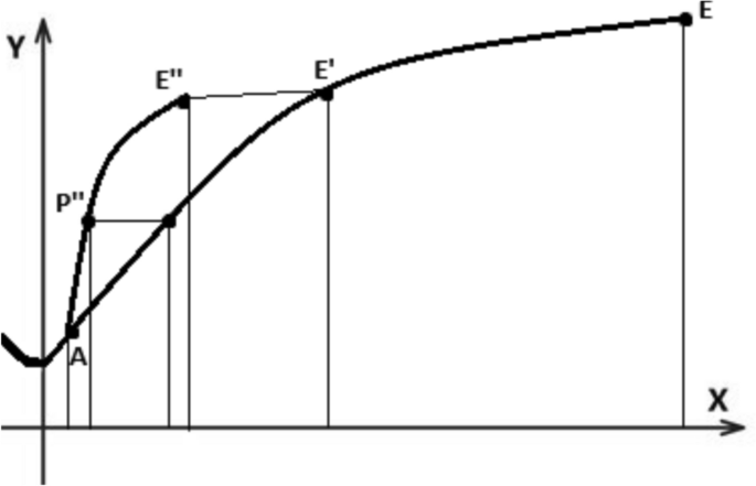
TIC nozzle design steps
The Method of Characteristics is implemented in its axisymmetric formulation similar to the description of Refer- ence [30], initialized with Dutton’s method [32].
3.1.3 Cone nozzle
The cone nozzle is designed as a straight-line contour extending from the throat to the desired exit area, with a slope defined by θE.
3.1.4 Isentropic case
The performance of the three nozzle designs will be evaluated based on the conditions at the exit plane. This was done to understand the losses associated with the different contours. A fourth theoretical contour was considered, assuming that the flow expands until it reaches ambient pressure and exits the nozzle at an angle of θE. The exit Mach number is given by Equation 8, considering isentropic expansion and thrust is only given by the momentum term.
3.2 Numerical studies
A two-dimensional control volume was constructed by integrating the designed nozzle contours, allowing the exhaust plume to develop under various operating altitudes, as shown in Figure 3, which defines the boundary conditions. The convergent is a symmetric part of the initial expansion arc.
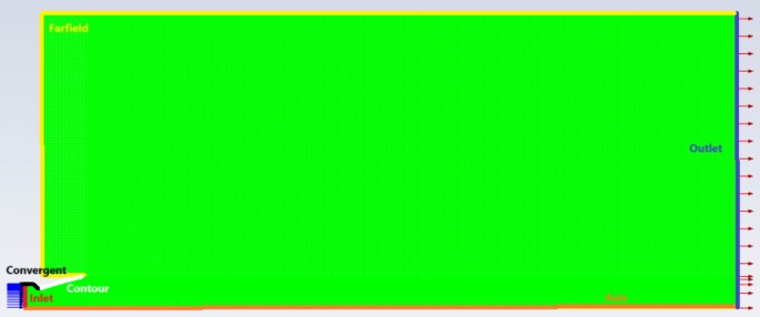
Control volume with boundary conditions
The control volume was meshed with higher density near the contour and inside the nozzle to resolve sharp property gradients, as shown in the close-up in Figure 4. All meshes contain 137108 nodes. The number of divisions of each edge was increased 1.2 and 1.5 times in order to perform a mesh independence study for the design operating conditions, corresponding to 197139 and 308169 nodes.
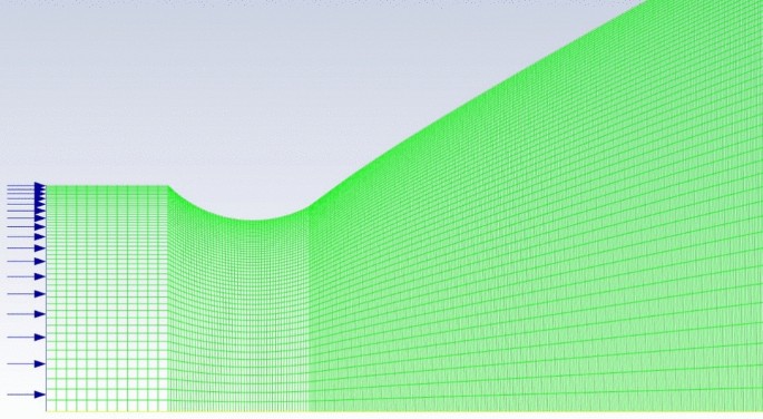
Control volume with boundary conditions
The several meshes were imported into the density based, steady, axisymmetric solver of Ansys Fluent. The density of the fluid was modeled as an ideal gas with γ = 1.4 and viscosity with a Sutherland’s three equation model. The SST k-ω was chosen for turbulence and the AUSM flux-type with high speed numerics.
An inlet total pressure of 1 MPa and total temperature of 1200 K was adopted with a supersonic initial pressure of 859580 Pa. The outlet was set for the temperature and pressure expected in the simulated altitude as per the International Standard Atmosphere [33].
Convergence was achieved when residuals fell below 5 × 10⁻⁴ for continuity and 1 × 10⁻⁴ for other variables, while the mass flow imbalance remained under 1% of the inlet value.
The numerical studies consider a nozzle with a throat radius of 1 mm, with properties such as thrust dependent on this value. The Mach disk distance and any other geometry value, will be presented as a dimensionless value, fraction of the throat radius.
4 Results and discussion
4.1 Flowfield analysis
Among the various properties visualized in Ansys Fluent, the Mach number contour was considered the most rele- vant, as it allows for the observation of expanding and exhaust flowfields while identifying shocks and expansion fans. Furthermore, it is possible to identify a Mach disk, which serves as a key characteristic of the exhaust plume.
A common characteristic among the three nozzle contours is that isentropic expansion is never fully achieved under any operating condition. As shown in Figure 5 for design conditions, there is always a weak oblique shock, created at the inflection point for the bell nozzles and at the throat for the cone nozzle. Nonetheless, these are weak oblique shocks, as observed by Hoffman [14], representing a trade-off between minimal thrust losses and a shorter nozzle.
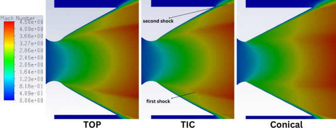
Mach number contours of the nozzles operating at design conditions
Furthermore, a second oblique shock is also observed, before the free boundary, between ambient and the exhaust plume. For the design operation the influence in performance is minimal and in overexpanding conditions, when the contour is not fully used to expand the flow, this secondary shock is imperceptible (Fig. 6).
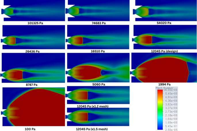
Mach number contour for the TOP nozzle operating at several altitudes
When the exhaust plume presents a Mach disk, its diameter increases for higher pressure ratios, except for extreme underexpansion operation, as suggested by Narayanan [3] and Cumber [4].
4.1.1 TOP nozzle flowfield
At ground-level operation (101 kPa), a single oblique shock originates from the inflection point, which also marks the exhaust plume’s separation from the contour. The second shocks appear when the most central zone of the expansion flow reaches the desired exit Mach number, at an ambient pressure of 54 kPa. In this case, the second shock is still forming inside the nozzle as the flow only fully attaches to the contour when ambient pressure drops to 26 kPa.
The first shock meets the second, upstream of the Mach disk, with the juncture point approaching the disk with increasing pressure ratios. At design operation, the shocks already do not meet contributing for the widening of the ex-haust plume. At overexpanding and design operation, the Mach diamond is concave, straight for slight underexpanding conditions and convex for the remaining underexpanded cases.
In all cases, the exhaust plume keeps expanding past the exit and to a Mach number further from that defined at design, reason behind the constant presence of the Mach disk and diamond structure.
Another observable phenomenon is the widening of the Mach diamond cells and moving downstream of the Mach disk as the operating pressure ratio increases. For the last two underexpanding scenarios, the turning of the exhaust plume may mean the control volume is small to properly simulate the so wide exhaust plume, but does not jeopardize the performance assessment. In these two cases, the Mach disk is located so far downstream that the first shock reflects off the axis before reaching the disk.
Different meshes were tested operating at the design pressure ratio, which results almost equal the Mach number contours of the base mesh, besides other properties, with only an almost imperceptible differences in the Mach disk thickness.
4.1.2 TIC nozzle flowfield
The TIC nozzle’s flowfield is similar to the TOP’s with some key difference at underexpansion, as in this case the exhaust plume is not as wide for the almost vacuum operation. Besides, at 2 kPa, the Mach disk has half the radius. The secondary shock at 54 kPa is even less perceivable and both meet at the Mach diamond at design.
4.1.3 Cone nozzle flowfield
The cone nozzle flowfield differs from the bell nozzles in several aspects. For instance, at ground-level operation, part of the cone is utilized, as this geometry lacks the initial arc-circle. Also, the second shock appears at lower pressure ratios, namely at an ambient pressure of 75 kPa.
Additionally, the Mach disk becomes convex near the overexpanded condition of 54 kPa. Its diameter decreases with increasing pressure ratios, eventually disappearing at design conditions, where no traces of a Mach disk are ob- served. The Mach diamond structure and the two weak shocks are still observable, meaning the flowfield inside the nozzle and the exhaust plume is never isentropic. Eventually, at an ambient pressure of 2 kPa a straight Mach disk appears.
Another particularity found for the cone nozzle flowfield is that the two shocks only meet when there is no Mach disk. In the other conditions both meet the Mach disk but at different points, probably contributing for the convexity of this structure. The expected double Mach diamond pattern was absent, consistent with Munday [7], whose cone nozzle had a low area ratio and half-angle.
4.2 Nozzle multi-altitude performance
4.2.1 TOP nozzle
At overexpanded conditions, the flow exits with an average Mach number higher than that of an isentropic expansion. Consequently, the exit pressure remains lower than ambient pressure, reducing thrust. For the two lowest pressure ratios, this phenomenon is so evident that the thrust coefficient is smaller than the isentropic case, which is particularly concerning as the last considered a constant exit angle of 26.87º and the CFD flowfield exhibits an average angle of the exit flow of 11.5º for these operating conditions.
Compared to the isentropic case, the TOP nozzle improves in performance as pressure ratios increase under over- expanded conditions but performs worse under underexpanded conditions. As expected, performance peaks at design conditions, where pressure starts to contribute positively to thrust.
The average exit Mach number at design was 3.410, slightly below the theoretical value of 3.5. But if the boundary layer thickness is removed, establishing a new and lower corrected exit area, the corrected area ratio will now correspond to a theoretical Mach number of 3.42. The average exit angle at design is of 22.0º which can reach gains of thrust (compared to the isentropic analysis) of up to 2.8 %, compensating the losses associated with the lower exit Mach number and oblique shocks. This average angle increases to 22.1º at the highest pressure ratio, representing a trend that correlates to the slight increase of Mach number, possible due to viscous interactions of the free boundary that reflect in the redirecting of the flow and boundary layer reduction near the exit transversal section.
4.2.2 TIC nozzle
The TIC nozzle’s performance closely matches the TOP nozzle’s, with slight superiority at pressure ratios farther from the design point, except between 75 kPa and 54 kPa. Not only the shocks in Figure 7 seem weaker, as the contour itself promotes a slightly thinner boundary layer which allows the nozzle to have higher exit Mach numbers.
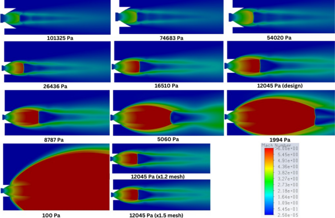
Mach number contour for the TIC nozzle operating at several altitudes
4.2.3 Cone nozzle
The cone nozzle’s performance data show higher Mach numbers. Under design and underexpanded conditions, values are closer to the expected design values due to a thinner boundary layer, as the smoother geometry reduces viscous effects.
The average exit angle for design operation is of 19.31º and increases to 20.06º at 0.1 kPa, slightly increasing total thrust. This phenomena can be correlated with the fact there’s no Mach disk in some operating condition, as the plume is not as wide (Tables 1, 2, 3).
4.3 Model validity
The mesh independence study was carried out for three rocket nozzles: TOP, TIC and cone, under design ambient pressure conditions to assess the sensitivity of flowfield and performance predictions to mesh refinement. Three levels of mesh resolution were considered: a baseline coarse mesh (x1), a medium mesh (x1.25), and a finer mesh (x1.5). The results across the three meshes, for each nozzle on Tables 4, 5 and 6, show only minor variations in key parameters, indicating that the flow is largely insensitive to the level of mesh refinement for the scope of this analysis.
Across all three nozzle configurations, the exit Mach number and exit pressure exhibited minimal changes with mesh refinement. For the TOP nozzle, Mexit slightly decreased from 3.411 to 3.405 as the mesh became finer, while Pexit increased marginally from 12430 Pa to 12534 Pa. Similar trends were observed in the TIC nozzle, where Mexit dropped from 3.425 to 3.405 and Pexit rose from 12400 Pa to 12745 Pa. In the Cone nozzle, both parameters remained nearly constant across all meshes, with Mexit around 3.433–3.434 and Pexit varying by only 40 Pa. These small differences confirm that the nozzle exit conditions are nearly mesh-independent, and any variation is within acceptable numerical uncertainty.
The subsonic boundary-layer thickness at the nozzle exit lip, which measures the radial distance from the exit lip’s wall to the location where Mach 1 is first reached, also showed excellent consistency. Its values remained within a narrow band (on the order of a 10– 4 fraction of the throat radius) across mesh resolutions, but did not follow the expected trend of thinning with increasing Mach number. This suggests the variations are numerical artifacts arising from mesh placement rather than physical changes in the flow. Additionally, other indicators and colormaps confirm that no significant changes in flowfield structures occur with finer meshes, further validating that these boundary-layer oscillations can be disregarded for the purposes of this study.
The position of the shock wave, or Mach disk, was also analyzed. For the TOP nozzle, the shock distance changed from 14.130 to 14.087 throat radius, amounting to a 5% variation relative to the throat radius, but less than 1% in absolute terms. For the TIC nozzle, the shock distance shifted slightly more, about 10% of the throat radius, but still remained under 1% in absolute change. In the cone nozzle, the shock was not captured for any mesh level, which is consistent with its flowfield indicating strong expansion and the absence of an internal shock. These findings confirm that shock structure is captured reliably even with the coarsest mesh, and mesh refinement does not significantly impact its position.
Regarding performance metrics, total thrust and thrust coefficient showed slight increases with mesh refinement to x1.25, followed by very small decreases at the x1.5 level. This lack of a consistent trend indicates that these values are not strongly influenced by mesh resolution. Interestingly, the coarse mesh tends to yield slightly more conservative estimates, which can be favorable in early-stage design evaluations. Specific impulse, however, demonstrated a gradual decrease with mesh refinement. This is explained by a small increase in predicted mass flow rate with finer meshes—up to 1.6% higher, which, when thrust remains nearly constant, results in a slightly reduced specific impulse.In summary, finer meshes yield marginally different predictions but minimally affect flowfield structure and per-formance. The differences in exit Mach number, pressure, boundary-layer thickness, shock position, and overall per- formance are sufficiently small that they do not justify the increased computational cost of finer meshes. Therefore, for the scope of this study, the coarse mesh (x1) is deemed adequate, providing accurate and conservative predictions while optimizing computational efficiency.
Though similar studies are scarce, Matsunaga [34] also observed anomalies like lower exit Mach numbers, where a minimum length nozzle contour for a Mach number of 4.5 at the test section is optimized, but in the first iterations the exit Mach number was of 4.45 due to the loss of effective area because of the boundary layer, which was thinner than in the present study as stagnation temperature was just 300 K (Fig. 8).
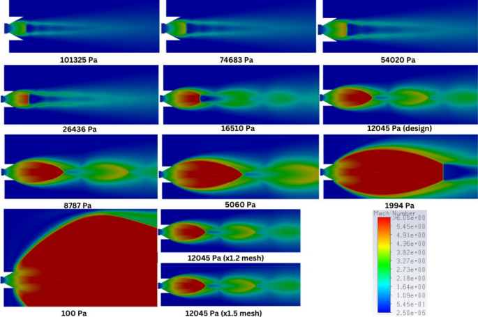
Mach number contour for the cone nozzle operating at several altitudes
During the study of overexpanding phenomena in TIC nozzles, Stark [16] performed some experiments, creating some Schlieren images from the exhaust plume, as in Figure 9, comparable to those obtained in this investigation noting that with higher divergence angles the disk is expected to form further from the nozzle, improving confidence in the results. Takahashi [15] results from a similar study of overexpanding TIC nozzles, also show good flowfield agreement. The structures observed in the cone nozzle at the design point agree with those of Hamedi [10].
Exhaust plume on (a,b) experimental [16] and (c,d) numerical overexpanded TIC nozzle
4.4 Comparison of TOP, TIC and cone nozzles performance
The performance data for the three nozzle geometries: TOP, TIC and cone, are summarized in Tables 1, 2, and 3, respectively. All configurations use a throat radius of 1 mm, and the tables include nozzle exit Mach number , thrust components from momentum and pressure, specific impulse, shock distance, thrust coefficient Cf and deviations from quasi-1d theoretical values. When comparing the nozzles, it becomes evident that the conical nozzle offers the highest performance across the majority of operating conditions. At the design backpressure of 12,045 Pa, the cone nozzle achieves a Cf of 1.391 and a specific impulse of 124.414 s. These values slightly exceed those of both the TOP (CF = 1.370, Is p = 122.851 s) and TIC (CF = 1.367, Is p = 122.813 s) nozzles. Even at lower ambient pressures where the flow is highly underexpanded, the cone nozzle maintains its performance advantage. For instance, at Pamb = 100 Pa, the conical nozzle reaches a CF of 1.474, outperforming both the TOP (1.390) and TIC (1.389) geometries under the same conditions. In overexpanded conditions, such as Pamb = 101,325 Pa, all nozzles experience performance degradation due to internal shocks. However, the cone nozzle again fares best, retaining a CF of 0.839 compared to 0.786 for the TOP and 0.830 for the TIC nozzle. This suggests that the cone design is more tolerant to ambient pressure effects, maintaining better alignment with ideal expansion conditions.
The difference in performance is also reflected in the quasi-1D deviation column. At the design pressure, the cone nozzle deviates by only 2.12% from the quasi-1D ideal, closely matched by the TOP (1.87%) and TIC (1.86%) nozzles. This consistency across geometries at optimal conditions reinforces the validity of the design point simulations.
Despite the cone nozzle’s superior efficiency and robustness across a wide range of pressures, its extended length may present practical limitations in aerospace applications where compactness and weight are critical. In contrast, the TOP and TIC nozzles, while slightly less efficient, offer more compact alternatives that still maintain competitive performance. These designs may therefore be preferred in systems with stringent spatial or mass constraints.
The TOP and TIC nozzles have 95% of the length of the cone nozzle, offering the potential for a 5% reduction in component weight while maintaining 98.48% and 98.44% of the thrust and specific impulse, respectively, for the TOP nozzle, and 98.31% and 98.63% of the same properties for the TIC nozzle. This indicates that the TOP nozzle can deliver slightly higher thrust than the TIC nozzle, although the latter is marginally more efficient in terms of specific impulse.
Flow structure analysis further reveals that the location of internal shocks is influenced by nozzle geometry. The more compact TOP and TIC designs exhibit shocks closer to the throat due to their sharper expansions, while the conical nozzle allows for a more gradual transition. As ambient pressure decreases and the nozzle becomes increasingly underexpanded, shocks move downstream and may even dissipate or exit the nozzle entirely. At very low ambient pressures, such as 100 Pa, the shock distance becomes large or undefined, and deviations from ideal performance are primarily due to expansion losses.
Figure 10shows that all nozzles behave similarly when integrated into an aerial vehicle operating at varying altitudes. Nonetheless, The TIC nozzle tends to perform slightly better then the TOP nozzle for most of the flight envelop of an ascending vehicle specially in overexpansion nearing design, but the cone nozzle always overperforms the previous for any operating condition. Near design, the tested nozzles even overperform what was expected by an isentropic expansion exiting with the same angle as the contour (27°), proving the effectiveness of the oblique shock within the nozzle that straightening the flow as it exits with a lower angle (22o for the TIC and TOP nozzles and 20o for the cone nozzle) that compensates related isentropic losses.
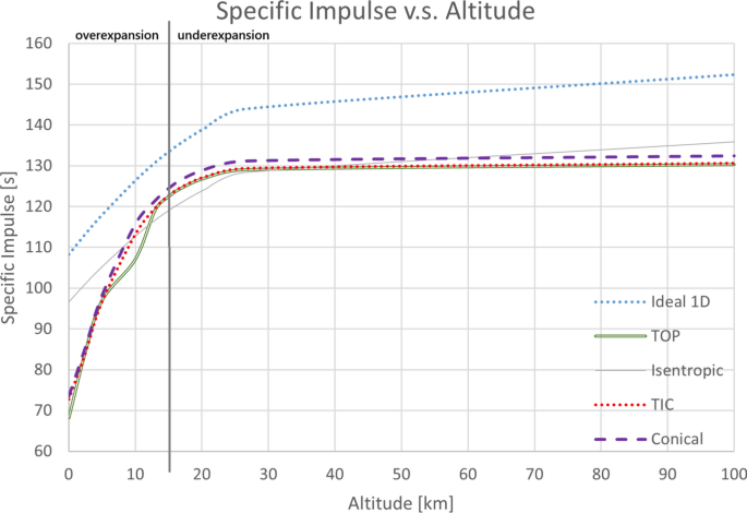
Specific impulse versus altitude during rocket ascension
For the TOP nozzle, the specific impulse obtained in this study (122.477 s) is higher than that predicted by the method of characteristics (119.921 s). This difference primarily stems from the divergence angle assumption in the method of characteristics (25°), whereas the CFD simulation predicts a lower angle. The reduced divergence angle not only compensates for isentropic losses but also improves flow redirection, leading to enhanced performance.
Regarding the thrust coefficient, in Figure 11, and the same chamber conditions, directly reflecting the produced thrust, the TIC nozzle also outperforms the TOP nozzle for the same region of overexpansion near an altitude of 10 km.
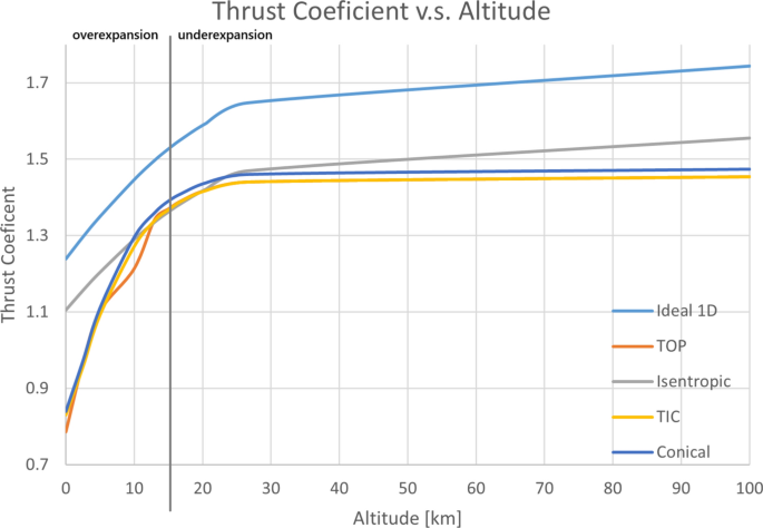
Thrust coefficient versus altitude during rocket ascension
Figure 12 illustrates the exit Mach number, highlighting how the nozzle’s fixed boundary causes underexpansion and associated losses. The TOP nozzle also struggles to expand the flow in the overexpading region near 10 km, compared to both TIC and cone nozzles, justifying the loss of some performance in this region. The effect of the boundary layer can also be observed, as the reduction in effective expanding area makes that the average exit Mach number never reaches the values of design (M = 3.5).
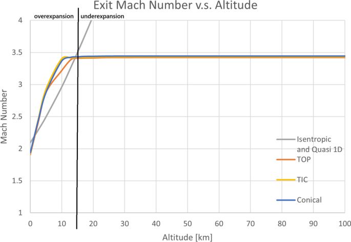
Mach number versus altitude during rocket ascension
Obviously, all nozzles under-perform greatly compared to a quasi-1D ideal nozzle, where the flow is expected to exit totally axial at ambient pressure. The present study is done carried assuming that a high flow exit angle is acceptable as a trade-off in having a shorter nozzle. Besides, the studied nozzles actually perform better then expected near their design point and infringe in small losses for underexpansion operation. It is in overexpanded operation that performance is poorer. In conclusion, the simulations show that while all three nozzle geometries perform well, the cone nozzle consistently delivers the highest efficiency. However, the compactness of the TOP and TIC nozzles offers a valuable trade-off in systems where volume or mass is a limiting factor.
5 Conclusion
This study is the first systematic evaluation of high-divergence angle axisymmetric nozzles (TOP, TIC, and cone) across multiple altitudes. It reveals how boundary layer development and shock wave interactions trade flow redirection for thrust loss. By using numerical tools, it was possible to observe key flowfield features, such as the interaction of two oblique shocks within highly divergent nozzles. These shocks affect the shape of the Mach disk, which appears concave when the shocks converge upstream and convex when they do not. The analysis shows that at the studied speeds, the boundary layer significantly impacts performance by reducing the effective exit area and velocity. The cone nozzle, with its straight contour, promotes less boundary layer growth compared to curved geometries, offering a modest performance advantage.
The findings confirm that when extremely short nozzles delivering already supersonic flow are acceptable, and a high divergence angle is desired, TOP, TIC and cone nozzles all serve as reliable thrust-producing configurations. Notably, internal shock interactions can straighten the flow without introducing substantial isentropic losses.
From an engineering perspective, TIC nozzles demonstrate slightly higher efficiency than the TOP contour while being approximately 5% shorter than the cone nozzle. This compactness can be particularly beneficial in upper-stage rocket integration where space is constrained. On the other hand, although the cone nozzle delivers less than a 2% increase in thrust and comes with a longer geometry, it is easier to manufacture. This makes it suitable for applications such as air-launched missiles, where structural simplicity and wide-operating envelopes are advantageous.
Future work should include experimental validation to further verify the numerical results, assess performance accuracy, and identify any potential physical phenomena not captured by the current CFD model that could influence the conclusions, including the SST k-ω turbulence model validity and accuracy.