Article Content
1 Introduction
PKMs typically consist of a moving platform that is connected to a fixed base by several actuated limbs. Due to the notable properties of PKMs, they are used extensively in industry and their applications are increasing, especially in advanced manufacturing [1,2,3,4]. Thus, in addition to addressing traditional challenges such as workspace analysis [5] and singularity avoidance [6], recent research has increasingly emphasized dynamic modeling [7], vibration analysis [8], and optimization and control of parallel kinematic machines (PKMs) [9,10,11,12]. Several methodologies have been explored to achieve dynamic modeling of PKMs, including the Newton–Euler formulation [13], the principle of virtual work [14], and the Gibbs–Appell formulation [15, 16]. The Gibbs–Appell formulation is particularly well suited for modeling closed-loop mechanisms with non-holonomic constraints due to its computational efficiency.
Due to high stiffness and accuracy, numerous CNC milling machines based on PKMs have been developed in the last two decades [17, 18]. However, one of the main drawbacks of PKMs is numerous singular configurations within their small workspace [19, 20]. Kinematic redundancy has been exploited to remedy this issue in PKMs [21,22,23]. A kinematically redundant parallel mechanism is a PKM that includes one or more additional active joints beyond the minimum required to control the moving platform’s degree of freedom. The redundancy provides extra mobility, which can be employed to improve performance criteria such as the avoidance of singularities, enhanced dexterity, and the reduction of actuator efforts [24].
In this regard, some PKMs with kinematic redundancy have been proposed in the literature for milling applications [25, 26]. A piecewise kinematically redundant planar PKM for a hybrid machine tool is proposed by Assal [25]. In this study, a redundancy resolution is provided for the mechanism to avoid singular configurations. A novel PKM with one translational and two rotational coupling degrees of freedom is analyzed by Zhang et al. [26] with application in hybrid kinematic machines.
In the 6-DOF PKMs for 5-axis CNC machine tools, the orientation of the moving platform (the angle along the tool axis) can be considered as the task space redundant degree of freedom [27]. Hence, this orientation can be handled to improve the performance of the mechanism by avoiding singular configurations. Dynamic trajectory planning problems associated with task space redundant degree of freedom of PKMs are investigated by Oen and Wang [28]. It is worth mentioning that, although kinematic redundancy can increase the singularity-free workspace, redundancy resolution and control of these mechanisms are still challenging [29, 30].
The main issue that needs to be addressed in the design of PKMs for the purpose of milling and machining is vibration analyses and the deviation of the mechanisms’ stiffness within the workspace [31,32,33]. Vibrations due to the milling forces can affect the accuracy of the machining process and more importantly can damage the structure of the machine and reduce the life of cutter [34]. Low stiffness in the link and joint components of PKMs can result in vibration of the moving platform and diminished accuracy during the milling process [35, 36]. In [37], an analytical study on the vibrations of a PKM is addressed. The authors have investigated the effect of variation in position and orientation of the moving platform on the change in stiffness of its supporting chain and mode shapes of the platform as well as the effects of different payloads. Ma et al. [38] have presented the vibration analysis for a novel portable hexapod machine tool attached to surfaces with unequal stiffness. Mechatronics modeling and forced vibration of a 2-DOF PKM in a 5-DOF hybrid machine tool are studied by Wu et al. [39]. In the case of mechanisms’ stiffness, Azulay et al. [40] have obtained the static and dynamic stiffness of a new PKM based on a 3 × PPRS topology via finite-element analysis. Considering the proposed 6-DOF PKM for 5-axis CNC machining, the roll angle is considered as a redundant task space degree of freedom for machining. It was shown that the resonance frequency undergoes variations for different joint-space configurations. An emulator-based prediction of dynamic stiffness for PKMs with kinematic redundancy is elaborated in [41].
In the design of PKMs for milling, another crucial factor is the natural frequency. This is a key parameter for PKMs utilized as CNC machine tools, as it illustrates the machine’s vibration tendencies. Mechanisms with higher natural frequencies can reach greater speed with desirable accuracy [42]. Therefore, many researchers have developed different approaches to calculate it. For example, a novel Jacobian-based natural frequency analysis method for PKMs is presented by Hoevenaars et al. [43] that calculates the lowest natural frequencies and their corresponding eigenmodes in an end-effector cartesian reference frame. Another approach for calculating the natural frequencies using global independent generalized displacement coordinates was introduced by Yang et al. [44]. Also, Gu et al. [45] have used kinematic redundancy to modulate the natural frequency of a planar PKM through adjusting geometric configuration. Inverse kinematic problem is then solved using a double-threshold method to keep the natural frequencies away from the excitation frequencies. Orekhov and Simaan [46] have investigated a real-time stiffness modulation through the combined use of kinematic redundancy and variable stiffness actuators.
This paper presents the dynamic and natural frequency analyses of a 3-PRR PKM for a two-degree-of-freedom task, where P and R represent prismatic and revolute joints, respectively, and the underlined joint represents actuation. Dynamic equations are formulated using the virtual work principle, and the optimization problem is formulated to obtain the moving platform’s orientation to avoid singular configurations. Flexibility in the prismatic joints and distal links is considered to model the vibrational behavior of the mechanism, enabling determination of its natural frequencies. Properly adjusting task space redundancy allows natural frequencies to be away from operation excitation frequencies, thus achieving effective vibration suppression and improved mechanism accuracy. The key contributions of this study are:
- Exploiting task space redundancy to avoid singularities and reduce actuator efforts.
- Developing an analytical approach for vibration and natural frequency analysis of PKMs with flexible joints and links.
- Enhancing milling accuracy by adjusting task space redundancy to tune natural frequencies away from those of external loads, thereby minimizing moving platform vibrations.
The results of this study contribute to the motion planning and control of PKMs, particularly in high-precision machining applications, and offer a versatile framework for similar dynamic analyses across other PKM configurations.
2 Kinematic analysis of the PKM
The planar PKM studied here is categorized as a 3-PRR type. As shown in Fig. 1, the PKM is composed of an equilateral triangular moving platform and three closed-loop kinematic chains. Each of the chains consists of an active prismatic joint and two passive revolute joints.
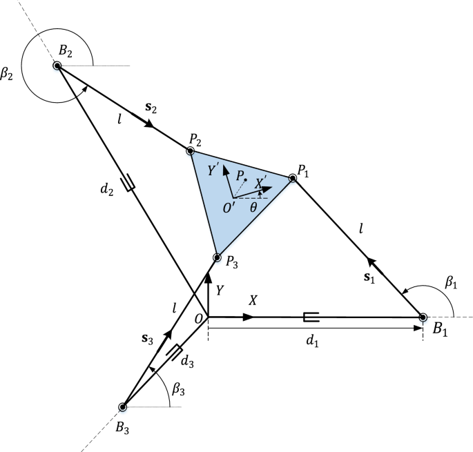
Schematic diagram of the planar 3-PRR PKM
As can be perceived from Fig. 1, a reference coordinate frame is attached to the base at the intersection of the prismatic actuators with its axis in the direction of the first actuator and axis is in the plane containing the mechanism. Also, a moving coordinate system is attached to the geometric center of the moving platform where axis is pointing to and axis is in the plane of the moving platform.
2.1 Position analysis
Position vector of an arbitrary point on the moving platform presented in reference coordinate system can be written as.
where is the position vector of the origin of the moving platform and the rotation matrix from the moving platform to the reference coordinate system is depicted by which is obtained as
Also, is the position vector of the corresponding arbitrary point with respect to the origin of the moving platform which can be written in the reference coordinate system as
Position vector of each corner point with respect to the origin in the moving coordinate system is considered as
where is the geometric parameter of the moving platform, namely, the distance between the point to each point . Also, can be obtained as
Now, the position vector of the point presented in the reference coordinate system can be calculated using Eqs. (1) and (4).
Also, position vector of each point in the reference coordinate system is written as
where is the lengths of the ith prismatic actuator. Moreover, the rotation matrix and the vector are expressed as
The orientation of the distal link can then be calculated as
where is the quadrant-corrected inverse tangent function [47].
Finally, using the condition , the lengths of the prismatic actuators can be calculated as
in which parameters and will be obtained as
Furthermore, the unit vector from point to is obtained as
2.2 Velocity analysis
In this subsection, an equation is derived to obtain the linear velocity of the point on the moving platform for a given translational velocity of the prismatic actuators. To do so, first the velocity vector of point is obtained by taking time derivative of Eq. (1).
where
Also, velocity of the point can be derived as
On the other hand, the velocity of point can be obtained as
where ωω is the angular velocity of the distal links with length and is the unit vector along the axis normal to the plane containing the mechanism.
Cross multiplication of both sides of Eq. (16) with leads to
which can be simplified to
Also, dot multiplication of both sides of Eq. (16) with yields
which means the projection of the vectors and on the vector has the same magnitude as the distal links are not deformable.
In sequence, applying Eqs. (13) and (15) to Eq. (19) yields the following equation which determines the relation between the velocity of the prismatic actuators and the velocity of the moving platform.
2.3 Acceleration analysis
The acceleration of an arbitrary point can be found by taking the derivative of Eq. (13) with respect to time and using the relation .
which can be rewritten as
in which is obtained as
The time derivative of Eq. (15) yields the acceleration of point as
Also, the time derivative of Eq. (20) leads to the following relation for
Furthermore, the angular acceleration of the distal links can be derived as follows by taking time derivative of Eq. (18)
3 Dynamic modeling of the PKM without considering flexibility
In this section, the dynamic equations of the corresponding planar PKM are derived, using the principle of virtual work. Accordingly, the virtual work of the inertia forces of the moving platform can be written as
where and are mass density and volume of the moving platform, respectively. Substituting Eqs. (13) and (22) into Eq. (27) leads to
which can be rewritten as
where the vector specifies the position and orientation of the moving platform. Also, the symmetric mass matrix in the above equation can be obtained as
Moreover, is the vector of the inertia forces and can be derived as
Since the moving coordinate system is rigidly attached to the center of mass of the moving platform, the term is equal to zero by the definition of the center of mass. Furthermore, the mass matrix can be simplified as
where is the centroidal mass moment of inertia of the platform about the axis of rotation, the one normal to the working plate.
Next, the virtual work of the actuator forces will be computed
Substituting Eq. (20) into (33) yields the following equation
where the vector is defined for simplicity. Using the principle of virtual work in dynamics, the following relation can be written for the corresponding PKM
The elements of the vector are independent. Thus, by applying an external force to the moving platform, the dynamic equations can be expressed in the following matrix form
in which the matrix will be obtained as
while the vector of the actuator forces is specified as
4 Natural frequency analysis considering link and join flexibility
In this section, vibration equations of the PKM will be obtained. In general, the flexibility of joints and links are two sources of vibration in a robotic system. Taking this into account, the flexibility of prismatic joints are modeled as a linear spring with stiffness and the distal links are considered as an Euler–Bernoulli beam as depicted in Fig. 2.
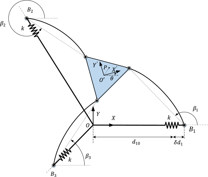
Schematic model of PKM with flexible joint and flexible distal links
4.1 Virtual work of the flexible joints
In this subsection, the virtual work of flexible joints modeled as linear springs is derived. Without loss of generality, each prismatic joint variable in Eq. (9) may be considered as a scalar function of the position and orientation of the moving platform as follows
Thus, by considering Eqs. (33) and (34), the virtual displacement of joint variables may be written as
where denotes the derivative of the function with respect to which is a row vector and can be written as
The spring force in each joint is
where is the spring constant and is a typical operating point for each prismatic actuator. Using the above equation, the term in Eq. (36) can be written as
Next, we introduce the vector function as follows to simplify the above equation
Using Taylor series expansion of the above function around a typical operating point , it may be linearized as
Now, the gradient of the vector function in Eq. (44) will be computed
which when evaluated in the operating point x0, it will be simplified as follows
Thus, with the aid of Eqs. (44) to (47), Eq. (43) will be simplified as follows
4.2 Virtual work of flexible distal links
The mass and stiffness matrices of the flexible distal links are obtained, in this subsection. For this purpose, flexible links are modeled using the assumed mode method.
In the assumed mode method, distal links are discretized using generalized coordinates. Accordingly, the position of an arbitrary point on the ith link can be written as
where the angle was calculated in Eq. (8) and is defined as
Also, the vector can be written as
where denotes the position of the corresponding point on the ith link in the undeformed state which is
Moreover, the vector is the deformation due to the flexibility and can be represented in terms of the product of mode shapes and generalized coordinates as
in which by considering mode shapes for each link, and can be expressed as follows
Time derivative of Eq. (49), the velocity of the point on the ith link is obtained as
Substituting from Eq. (15) into Eq. (56) yields the following relation
where the vector of coordinates is considered as
Time derivative of Eq. (58) yields the acceleration vector as
where is obtained as
Now, the virtual work of inertia forces of the ith flexible distal link can be written as.
Substitution of Eqs. (57) and (59) into the above equation leads to
which can be rewritten in the following compact form
where the matrix and the vector are defined as
The components of the vector are not independent. The independent coordinate vector is defined as
Considering Eqs. (18) and (20), the relation between and is obtained as
where
In Eq. (68), is defined for applying the cross product of vectors as follows
where and are the components of the vector .
Time derivative of Eq. (67) yields the following relation between and
in which after some calculations the vector will be derived as
Using Eqs. (67) and (70), the virtual work of the ith flexible link given in Eq. (63) is written as
Defining and as
Equation (72) can be written in the following partitioned form
Next, the virtual work of elastic forces corresponding to each flexible link will be calculated using the Euler–Bernoulli beam theory.
where is the transverse displacement of each link which can be determined from the second component of the vector evaluated in Eq. (53) and is the flexural stiffness of the flexible distal links. With the aid of Eq. (75), the components of the stiffness matrix for the ith link can be obtained as
4.3 Vibration equations of the PKM
Using the principle of virtual work for the overall rigid and flexible parts, the vibration equations of the PKM can be written as
where the vector is defined as
Also, the mass matrices, , are obtained as
in which their elements are defined in Eqs. (32) and (74). Furthermore, the matrix in Eq. (77) is
whose elements for each distal link are obtained in Eq. (76). Moreover, the vectors, , are found as
Next, consider the vector in Eq. (77). This vector is a function of the vector of degrees of freedom of the associated mechanism and its time derivative . Specifically, all of its terms have quadratic multiplication factor of the vector . Thus, Taylor series expansion of this function for linearization around a typical equilibrium point will be zero as shown below
Finally, by introducing , the following form of linearized equations of motion will be obtained
in which the mass matrix and the stiffness matrix of the linearized equations can be calculated from the following relations
5 Simulation and Results
In the presented simulations, the distal links are assumed to be made of steel bar of rectangular cross section. The geometric parameters are listed in Table 1.
In the first simulation, an elliptical trajectory is considered for the position of the center of the moving platform, while its orientation is optimized to minimize the condition number of the matrix along the path. To achieve this, an optimization problem is solved at each time step to minimize the condition number as given:
where means the condition number of the matrix N.
The optimal orientation of the moving platform, obtained at each time step, is then used to numerically compute the angular velocities and accelerations of the moving platform using numerical methods. These kinematic quantities are subsequently used to solve the inverse dynamics problem, providing the actuator forces required at each time step.
The optimization problem in each time interval is solved using fmincon function, included in MATLAB’s optimization toolbox and the optimal task space redundant degree of freedom is obtained. However, the more improved techniques proposed in [48, 49] can be beneficial for resolving redundancy issues. Additionally, the real-time redundancy resolution proposed in our prior work [50] can be employed to acquire the task space redundant degree of freedom.
For the presented simulation in this section, the external force in Eq. (36) is chosen to be . Moreover, the ellipse is selected as
The obtained optimal orientation of the end effector through the desired trajectory is depicted in Fig. 3. As observed, the optimized orientation of the platform follows a smooth and continuous trajectory, varying from approximately 45 to 85 degrees. This gradual change indicates a stable transition that supports consistent performance throughout the task.
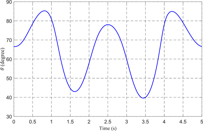
Optimal orientation of the moving platform (task space redundant degree of freedom) versus time
Figure 4 illustrates the inverse of the condition number for the corresponding optimal orientation and also a constant orientation of the moving platform at . The figure shows that the inverse of the condition number of matrix N ranges from approximately 0.04 to 0.1 for the optimized orientation, whereas it remains below 0.05 along the entire path when the orientation is kept constant. This indicates improved numerical conditioning in the optimized case. Since the optimization process explicitly minimizes the condition number of N, its inverse is expectedly higher along the trajectory, reflecting better manipulability and reduced sensitivity to errors.
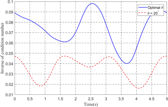
The comparison of the inverse of condition number for the optimal and constant orientation of the moving platform
Finally, in Fig. 5, actuator forces are shown when the platform moves along the elliptic path with the optimal orientation and with a constant orientation at . As shown in the figure, when the moving platform orientation is held constant at 20 degrees, the maximum absolute actuator forces reach approximately 1600 N, 1700 N, and 1900 N for actuators 1, 2, and 3, respectively. In contrast, under the optimized orientation strategy, the maximum absolute force across all three actuators is significantly reduced to around 500 N. This substantial decrease demonstrates the effectiveness of the optimal orientation in distributing the load more efficiently, thereby reducing actuator effort and potentially enhancing system longevity and energy efficiency.
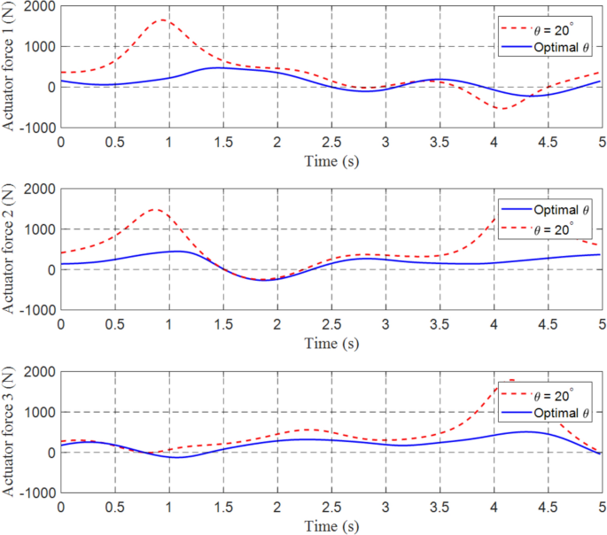
The comparison of the actuator forces for the optimal and constant orientation of the moving platform
In the next simulation, we obtain natural frequencies of the associated mechanism in a rectangular region. Accordingly, and coordinates of the origin of the end effector, , are considered to be in the range of and its orientation is fixed at . For the distal links, the first mode shape of a pin-pin beam is used in the assumed mode method, i.e.,. Hence, the total number of degrees of freedom and also the number of natural frequencies will be equal to 6. The distribution of the natural frequencies of the flexible joints and links in the corresponding region is depicted in Fig. 6. The figure illustrates that the natural frequencies associated with the flexible joints, represented by the first three modes, lie within the range of 40 to 72 Hz. In contrast, the natural frequencies corresponding to the flexible links, depicted by the last three modes, fall within a higher range of 80 to 240 Hz. This distinction highlights the differing dynamic characteristics of the joints and links, with the links exhibiting greater stiffness and thus higher natural frequencies.
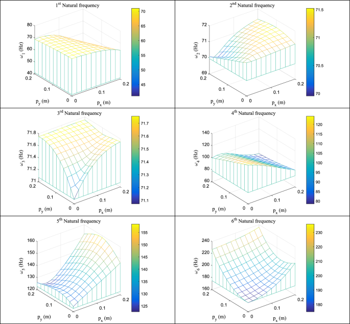
The distribution of the natural frequencies of the flexible joints and links in a rectangular region with a fixed orientation of the moving platform
Next, the effect of orientation of the moving platform on natural frequencies of the mechanism is investigated. To do so, the position of the end effector is fixed at and in the reference frame. Natural frequencies are then obtained for different orientations of the end effector. In Fig. 7, natural frequencies of the flexible joints are depicted. It is observed that at , the first natural frequency is zero which is due to the singularity of the mechanism. Specifically, the condition number of the matrix in Eq. (36) will be zero in this case. Also, Fig. 8 illustrates natural frequencies of the flexible links which are much larger than those obtained for the joints.
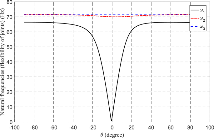
Natural frequencies of flexible joints for a fixed position and different orientations of the end effector
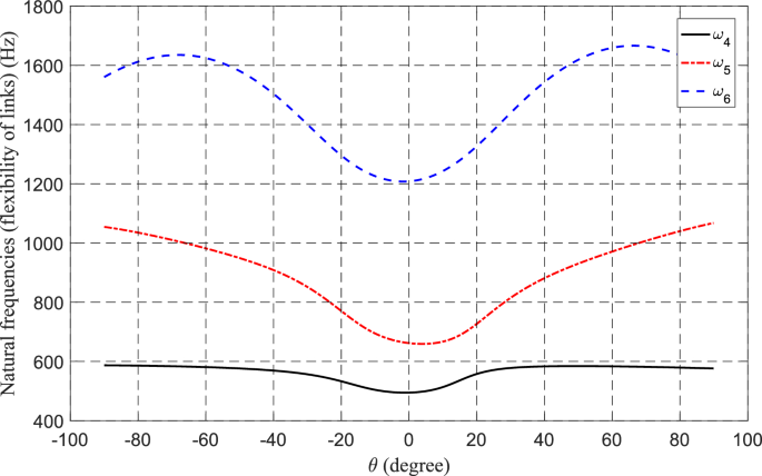
Natural frequencies of flexible links for a fixed position and different orientations of the end effector
In these two simulations, we observed that natural frequencies of the flexible links are in a range much larger than those of the flexible joints. Hence, it is more probable that the frequency of excitation of external forces be in the range of natural frequencies of flexible joints. Therefore, flexibility of joints is more significant for design consideration of the associated mechanism in practical situations to avoid resonance. Moreover, this observation supports the modeling choice of using only the first mode for flexible links. Since higher modes correspond to even higher natural frequencies, well beyond the typical excitation range, they contribute minimally to the system’s response and can be omitted without compromising accuracy.
In the final simulation, the effect of excitation frequency of external forces on the response of the mechanism will be demonstrated. Here, we consider a structural damping matrix for the mechanism which is a linear combination of the stiffness and mass matrices in Eq. (87)
The coefficients and in the above equation can be calculated from specified damping ratios and for the ith and jth modes, respectively, as [51]
in which and are the ith and jth natural frequencies, respectively.
Now, we consider a typical configuration of the moving platform, namely, with two different initial orientations . Figure 9 displays the changes in absolute values of the horizontal and vertical displacements and orientation of the moving platform form the operating configuration versus excitation frequency of the external force. Also, in Fig. 10, absolute values of the middle point displacements of the flexible distal links for different values of excitation frequencies are demonstrated. Here, the external force is considered to be harmonic with amplitude of 700 N applied in the horizontal direction of the reference frame. Moreover, the coefficients and in Eq. (93) are determined by selecting the damping ratios to be 1% for the first and third modes. It is obvious from both figures that the orientation of the moving platform will change the frequencies at which the peak values of the responses will occur.
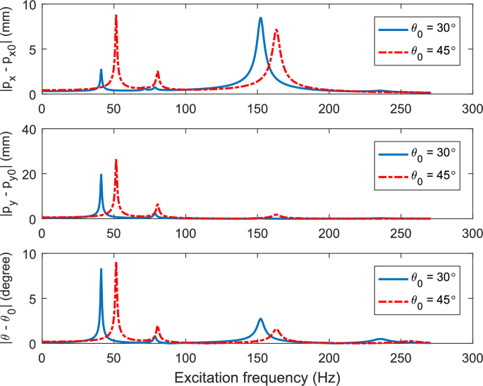
The changes in absolute values of the horizontal and vertical displacements and orientation of the moving platform form the operating configuration versus excitation frequency of the external force
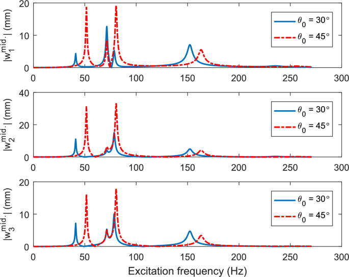
Absolute values of the middle point displacements of the flexible distal links versus excitation frequency of the external force
The developed theoretical formulation in this research can be used for designing and motion planning PKMs for industrial applications such as milling. The stiffness constants of the flexible links and joins can be identified and used with the provided formulation to estimate the natural frequencies and avoid vibrations by adjusting the orientation of the moving platform as redundant degrees of freedom [52].
As mentioned before, the assumed mode method is used in this research to model flexible distal links. Selecting the proper modes for flexible distal links is not an easy task [53]. Thus, finite-element method [54] is used as an alternative technique in the literature for modeling flexible manipulators. However, in this method, the bending moment and stress is discontinuous and due to the large number of degrees of freedom, the computational cost of calculations is high.
6 Conclusion
This paper presented a comprehensive formulation for the dynamic modeling of a planar PKM. It investigated the effect of using the orientation of the moving platform as a redundant degree of freedom to reduce actuator efforts. The study is particularly relevant for applications such as milling, where high accuracy and two translational degrees of freedom are essential.
The vibration behavior of the mechanism was also analyzed to address accuracy, an essential aspect in the design of milling machine tools. The model incorporates flexibility in distal links and the active prismatic joints. Distal links are modeled as Euler–Bernoulli beams with pinned–pinned boundary conditions, while joint flexibility is represented using linear spring models. The corresponding mass and stiffness matrices are obtained through linearization, and the natural frequencies of the mechanism are then computed. Simulation results led to the following key findings:
- Reduction in Actuator Forces: By adjusting the orientation of the moving platform, actuator forces were significantly reduced, demonstrating the benefit of task space redundancy in avoiding singular configurations.
- Influence of Joint vs. Link Flexibility: The natural frequencies associated with joint flexibility were lower than those resulting from distal link flexibility, highlighting the dominant role of joint compliance in the mechanism’s dynamic response.
- Tuning Natural Frequencies through Orientation: Simulation results confirmed that the natural frequencies of the mechanism can be modified by changing the orientation of the moving platform. This tunability enables vibration reduction, which is crucial for achieving high-precision milling.
The proposed formulation can be used to design PKMs for high accuracy milling, considering both singularities and natural frequencies.
It is notable to mention that creating an experimental setup to obtain constants for joint and link flexibility through an identification process and to determine the vibration behavior at different locations in the workspace can provide some promising future in this context. The developed model can then be used for motion planning to minimize deviations of the moving platform under external forces.