Article Content
1 Introduction
1.1 Exploring the advancements and applications of VLC technology
VLC is an innovative technology designed to meet the growing demand for higher bandwidth while reducing radio frequency (RF) spectrum congestion (Wang et al. 2017). Particularly suited for indoor applications, VLC uses light-emitting diodes (LEDs) for sending data and photodiodes (PDs) to receive and convert light signals into electrical signals, operating with intensity modulation with direct detection (IM/DD) (Zhang et al. 2021). VLC is inherently safe for human vision and offers adjustable light intensity through dimming, making it adaptable to various applications (Beguni et al. 2021).
VLC supports various use cases, including indoor positioning, high-speed video streaming, data broadcasting, and underwater communication (Furqan Ali and Jayakody 2023; Zenhom et al. 2018). It is especially useful in environments prone to high electromagnetic interference, like hospitals, aviation, and vehicle-to-vehicle communication (Almadani et al. 2020). Additionally, VLC enables seamless audio transmission, supporting smooth music streaming and compatibility with ITU and 3GPP audio standards (Zenhom et al. 2019).
By leveraging LEDs for both lighting and data transmission, VLC provides a dual-purpose solution. It is a cost-effective technology that operates without the need for licensing (Wang et al. 2017). A key advantage of VLC is its secure data transmission, as light signals are confined to physical spaces and cannot penetrate walls, offering enhanced privacy and security. Advancements like wavelength division multiplexing position VLC at the vanguard of next-generation communication systems, playing a crucial role in the development of future mobile networks, including 6G (Tariq et al. 2020).
Combining versatility, efficiency, and security, VLC offers a transformative solution to modern communication challenges, serving as a robust alternative to RF-based systems while addressing the increasing need for reliable, high-bandwidth data transmission (Sobhy et al. 2020).
1.2 Techniques for achieving real unipolar signals in VLC systems using multicarrier modulation
In VLC systems, signals conveyed using LEDs must be both real and unipolar to align with the characteristics of LEDs. To achieve this, various single-carrier modulation techniques such as on–off keying, binary phase shift keying, and pulse position modulation are employed. However, these techniques often limit the achievable data rates. To overcome this limitation and enable higher data rates, multicarrier modulation (MCM) techniques, specifically orthogonal frequency division multiplexing (OFDM), are adopted in VLC systems (Zenhom et al. 2024b).
Traditional OFDM, however, is not directly applicable to VLC systems due to its bipolar complex output. This challenge is addressed by adopting optical orthogonal frequency division multiplexing (O-OFDM), which ensures the transmitted signals are real bipolar. O-OFDM achieves this by implementing Hermitian symmetry (HS) prior performing the inverse fast Fourier transform (IFFT). HS involves configuring the modulated symbols such that the first half of the IFFT utilizes complex modulated symbols (CS), while the second portion uses their reversed complex conjugates (RCS). This arrangement ensures the output of the IFFT is a real bipolar signal but reduces the data rate to half of that in traditional OFDM (Farid et al. 2023).
While the IFFT output is real, it remains bipolar. To transform this bipolar signal into a unipolar format appropriate for VLC systems, several techniques are employed, including direct current biased O-OFDM (DCO-OFDM), asymmetrically clipped O-OFDM (ACO-OFDM), unipolar OFDM (U-OFDM), and FLIP-OFDM. Each of these techniques has unique characteristics and trade-offs (Zenhom et al. 2024a).
DCO-OFDM uses direct current (DC) bias to convert bipolar signals to a unipolar format. This method supports high data rates but can negatively impact power efficiency and bit error rate (BER) performance. When HS is applied, the data transmission rate is reduced by 50% compared to traditional OFDM (Elbakry et al. 2022).
In contrast, U-OFDM and FLIP-OFDM split the real bipolar signal into two consecutive portions: the first contains positive values, and the second includes negative ones. This method obviates the requirement for a DC bias, facilitating unipolar transformation while maintaining data integrity. However, similar to DCO-OFDM, HS reduces the data rate by 50%, and using the two consecutive frames leads to a decrease of 50% compared to DCO-OFDM. Despite this, U-OFDM and FLIP-OFDM demonstrate superior BER performance in contrast to DCO-OFDM (Mohammed et al. 2021).
ACO-OFDM employs an alternative method by utilizing only odd subcarriers to transmit CS, rendering the other subcarriers inactive in the initial segment of the IFFT. The following portion of the IFFT uses the FCS from the initial half. This configuration enables ACO-OFDM to truncate negative samples without causing distortion, establishing unipolar conversion without requiring a DC bias. The transmission rate is minimized by fifty percent relative to DCO-OFDM. ACO-OFDM transmits real unipolar signals within only one frame, providing improved BER performance (Khalaf et al. 2023).
In contrast to U-OFDM and FLIP-OFDM, ACO-OFDM exhibits superior power efficiency by transmitting data within only one frame instead of necessitating two frames. Additionally, it achieves similar BER execution to FLIP and U-OFDM while outperforming DCO-OFDM. ACO-OFDM’s reduced sophistication and straightforward deployment render it a practical choice for VLC systems, particularly in applications requiring efficient and reliable communication (Khalaf et al. 2023).
1.3 Challenges in real-world VLC implementations
VLC systems offer significant advantages for high-speed wireless communication. However, real-world implementation is hindered by challenges such as ambient light interference, receiver alignment issues, mobility constraints, bandwidth limitations, PAPR distortions, hardware constraints, and multi-user interference (MUI). Addressing these challenges is essential for making VLC systems practical and scalable across diverse applications.
One major issue is ambient light interference, where external light sources such as sunlight and artificial lighting introduce noise that degrades signal quality. A study proposed a model incorporating optical filtering and adaptive thresholding to minimize interference, improving signal detection in VLC systems (Verma et al. 2014). Another approach demonstrated multi-domain suppression techniques that utilize spatial, temporal, and frequency-domain filtering to mitigate ambient light noise, significantly enhancing VLC performance in dynamic environments (Ahmed et al. 2022).
Receiver alignment issues also affect VLC performance due to the necessity of maintaining a strong line-of-sight (LOS) or controlled reflections. Any misalignment between the transmitter and receiver leads to increased bit error rate (BER) and performance degradation. Recent advances in the optical phased array (OPA) beam steering enable dynamic adjustment of the receiver’s field of view, helping maintain stable connectivity (Nikkhah et al. 2013). Additionally, a liquid–crystal-based optical phased array system was developed for visible light beam steering, effectively redirecting optical signals in real-time and improving system robustness in mobile VLC applications (Notaros et al. 2019).
Another limitation is coverage and mobility constraints, as VLC signals are highly directional and struggle to provide seamless communication in mobile scenarios. reconfigurable intelligent surfaces (RIS) have been explored to manipulate incident light and extend VLC coverage, enhancing system adaptability in dynamic environments (Abdeljabar et al. 2025). Another promising solution is hybrid VLC-RF systems, where RF communication ensures seamless connectivity when VLC link quality deteriorates, making this approach particularly beneficial for vehicular communication and innovative indoor spaces (Abuella et al. 2021).
Hardware limitations remain a significant concern, particularly in developing high-speed photodetectors and LED drivers. A study introduced a low-power, high-speed VLC receiver system-on-chip (SoC) with ambient light rejection and post-equalization, enhancing signal robustness (Li et al. 2018). Moreover, Gallium Nitride (GaN)-based LEDs have gained attention for their superior modulation capabilities, faster response times, and higher energy efficiency, making them a preferred choice for high-speed VLC applications (Griffiths et al. 2020).
Multi-user interference (MUI) is a challenge in VLC networks, where multiple users share the same optical channel, leading to performance degradation. Interference alignment strategies have been introduced to efficiently allocate resources and enhance spectral efficiency in multi-user VLC systems (Sobhy et al. 2025). Additionally, an adaptive superimposed constellation algorithm (ASCA) has been developed for NOMA-based VLC systems, improving power allocation and dynamically selecting modulation orders to enhance system performance while reducing the symbol error rate (SER) (Zhao et al. 2016).
Finally, PAPR and nonlinear distortions further challenge VLC implementation. A study analyzed pre-distortion and post-distortion techniques, demonstrating that these approaches significantly reduce LED nonlinearities and enhance signal fidelity in VLC systems (Kumar and Singh 2024). Additionally, a hybrid method combining precoding and companding has been shown to reduce PAPR while alleviating nonlinearity effectively, further improving overall system performance (Khalaf et al. 2023).
Addressing these challenges is essential for advancing VLC technology toward widespread adoption. The integration of adaptive signal processing, optical beam steering, RIS-enhanced coverage solutions, hybrid VLC-RF architectures, high-speed LED advancements, interference mitigation strategies, and PAPR mitigation techniques plays a crucial role in enhancing VLC system performance. These innovations make VLC systems more reliable, scalable, and practical for real-world applications. In this context, this article introduces a novel PAPR mitigation technique designed to address the high PAPR issue in VLC systems. The following subsection provides an overview of the primary classifications of PAPR reduction techniques employed in MCM for VLC systems.
1.4 PAPR reduction techniques for MCM in VLC systems
MCM techniques enhance data transmission rates and mitigate multipath effects in IM/DD systems. However, a significant challenge with MCM is its high peak-to-average power ratio (PAPR), which can degrade system performance. Addressing this issue is crucial for transmitting real unipolar signals within the LED’s linear operating region, ensuring reliable communication in VLC systems. Strategies for PAPR reduction in MCM fall into three primary categories: adding signal techniques (AST), multiple signal representation (MSR), and precoding techniques (PCT) (Farid et al. 2023; Hameed et al. 2021; Zenhom et al. 2025).
Adding signal techniques (AST) include methods such as clipping, nonlinear companding techniques (NCT), and constellation shaping. The clipping technique truncates signal peaks to reduce PAPR but introduces noise, which can affect system performance. Constellation shaping modifies the signal’s structure to reduce peak power, though it may also introduce noise. Nonlinear companding techniques, such as A-law and μ-law companding, apply mathematical functions to compress signal peaks while enhancing lower-power signals, thereby preserving overall signal quality. Among these approaches, nonlinear companding stands out as particularly effective due to its ability to balance PAPR reduction with minimal impact on signal integrity (Xin et al. 2019).
Multiple signal representation (MSR) techniques generate diverse signal variants by altering amplitude, phase, or data arrangements. Examples include selective mapping and partial transmit sequence. While these approaches can achieve PAPR reduction, they require extensive calculations and additional data transmission to synchronize the receiver, consuming valuable bandwidth. Since VLC systems using O-OFDM are already bandwidth-constrained, MSR techniques are less suitable for this application (Valluri et al. 2020).
Precoding techniques (PCT) offer an efficient solution for PAPR reduction. These methods reduce peak power without requiring additional data or excessive computational complexity. Furthermore, they maintain signal accuracy, making them highly suitable for VLC systems, particularly when bandwidth and processing resources are limited (Taha et al. 2022). In summary, while MSR techniques face limitations due to their complexity and the need for additional information transmission, nonlinear companding and precoding techniques emerge as practical and effective solutions for reducing PAPR in MCM-based VLC systems. These approaches balance efficiency and performance, making them well-suited for modern VLC applications (Hameed et al. 2021).
Based on the analysis of related work, nonlinear companding techniques like μ-law and A-law, as described in (Mohammed et al. 2021; Niwareeba et al. 2022; Wang et al. 2020), as well as clipping technique, as described in (Elaage et al. 2024), have been identified as effective methods for addressing the PAPR issue. These techniques are particularly advantageous because they do not require side information and add no extra complexity. This research will use these methods as benchmarks for comparison with the proposed techniques.
1.5 Key contributions of the study
ACO-OFDM offers several benefits over other O-OFDM techniques, particularly in terms of BER performance, power efficiency, and data transmission using LEDs within a single frame. However, like other O-OFDM methods, it faces the issue of high PAPR. This research introduces innovative solutions to mitigate these challenges. Our contributions are as follows:
- First Contribution: Initially, various precoding techniques (PCTs), including Discrete Sine Transform (DST), Discrete Cosine Transform (DCT), Discrete Hartley Transform (DHT), Vandermonde-like Matrix (VLM), and Walsh-Hadamard Transform (WHT), are evaluated. Among these, the WHT-based precoding demonstrates BER performance comparable to conventional ACO-OFDM. However, when integrated with the proposed noise cancellation approach, the WHT-based method outperforms all other techniques and closely matches the performance of noise-canceled ACO-OFDM. Therefore, this research combines WHT as a precoding technique with three nonlinear companding techniques to further enhance PAPR and optimize overall system performance.
- Second Contribution: To further improve BER performance, we propose two noise-cancellation receiver models that mitigate clipping and channel noise. These approaches significantly improve the overall system robustness, addressing common imperfections in practical VLC systems.
- Third Contribution: The integration of PAPR reduction techniques with noise-cancellation receivers forms a comprehensive optimization framework where both PAPR and BER are optimized in parallel. This innovative integration minimizes compromises between signal distortion and error probability, particularly in challenging communication environments.
- Fourth Contribution: The study presents a comprehensive comparison of existing techniques in the field, incorporating traditional methods (μ-law, A-law, clipping) alongside our novel hybrid method. Unlike earlier works that use simple PAPR reduction techniques, our approach integrates precoding, companding, and noise-cancellation methods, yielding superior performance. Our hybrid method outperforms traditional methods in both PAPR reduction and BER improvement.
The structure of the paper is outlined as follows: Sect. 2 introduces the conventional ACO-OFDM system model alongside the proposed PAPR reduction techniques and optimal BER receiver strategies. Section 3 presents the simulation results, evaluates the proposed methods’ performance, and compares them with related studies. Lastly, Sect. 4 concludes by summarizing the key findings of the research.
2 System model
Asymmetrically Clipped Optical OFDM (ACO-OFDM) is a prominent technique in optical communication systems that eliminates the demand for DC bias, thereby enhancing power efficiency (Zenhom et al. 2024a). Unlike DCO-OFDM (Hasan 2013), ACO-OFDM generates an output clipped at zero without damaging data integrity. This unique property allows for more efficient utilization of optical power, making ACO-OFDM an attractive option for various optical communication applications.
Notation Bold lowercase letters denote vectors, and bold uppercase letters indicate matrices. The notation signifies the transposition of a vector or matrix, signifies the complex conjugate of , and denotes the expected value.
2.1 Conventional ACO-OFDM
The serial input data is mapped to serial complex modulated symbols as shown in Fig. 1a by any mapping technique such as QAM modulation , where the FFT/IFFT size. The complex symbols after the serial to the parallel stage are denoted as ,
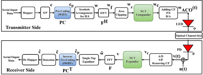
Block diagram of: a Standard ACO-OFDM (excluding the blue and green boxes), b Walsh Hadmard transform precoded ACO-OFDM (including blue boxes) and c Nonlinear companding methodology (including green boxes)
The complex symbols () are arranged in the frequency domain according to the Hermitian Symmetry (HS) requirement, producing the signal w. This arrangement ensures a real-valued output when applied to the IFFT stage. Specifically, , and the modulated symbols () from the mapping stage are placed at the odd-indexed positions of w, while the even-indexed positions are intentionally set to null. The final N-sized signal, structured according to HS, is described as:
The arrangement symbol is applied to the IFFT, to convert into in the time domain, as illustrated in Eq. 3.
where is the IFFT matrix and defined as , where the FFT matrix with N × N size as dedicated in Eq. 4 and each element of the FFT matrix is defined in Eq. 5.
where represents the row index of the FFT matrix, which corresponds to the frequency domain index. It indicates different frequency components in the transformed domain, and represents the column index of the FFT matrix, which corresponds to the time domain index. It means different time samples in the original signal before transformation. Thus, the FFT matrix transforms a vector from the time domain (-indexed) to the frequency domain ( -indexed).
For instance, where N = 4, the corresponding FFT matrix is shown as follows:
Before transmission, the generated signal from the IFFT process is applied to zero clipping, producing a signal denoted as . This process coverts the bipolar characteristics of , ensuring the signal becomes unipolar to meet the requirements of IM/DD. Prior to using the LED to transform the electrical signal into an optical signal, a cyclic prefix (CP) is appended to the signal. The CP’s length must be equal to the number of channel impulse response (CIR) taps to prevent inter-symbol interference. The Ф -tap CIR is represented as (Elkarim et al. 2015):
The channel impulse can be divided into a line of sight (LOS) and non-line of sight (NLOS), as shown in Fig. 2, the LOS response can be given as (Lee et al. 2011),
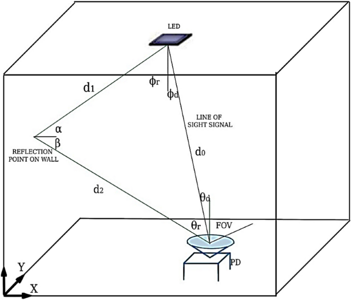
Diagram of the multipath VLC channel model
In this context, represents the area of the photodetector, while Lambertian emission order is referred to as . The optical collector gain is given by , using a refractive index and field of view angle , and the optical filter gain is expressed as . The angles of incidence and emission are represented by ϴ and ϕ, respectively, where ϕ < , ϴ < , and > > . The distance refers to the separation of the source from the receiver. is determined using the following equation (Mohammed and Elkarim 2015):
where φ denotes as the half-power angle of the LED.
The NLOS response can be given as (Abd Elkarim et al. 2021),
where and are the length from the LED to the reflection spot and from the reflection spot to the recipient, respectively. is the reflection coefficient of the wall. is the reflective area of the wall. , , α, β are angles related to the geometry of reflection. After adding the significant CP, the samples are subsequently serialised and passed through a digital-to-analog conversion stage (D/A).
After traversing the optical channel, the transmitted visible light signal is received by the PD, which transforms it into an analog electrical signal. This analog signal is digitized at the receiver using an analog-to-digital converter (A/D). Following digitization, the CP is removed from the received samples, and the data is reorganized into a serial-to-parallel format through the S/P stage. The system presumes that the channel response is precisely characterized by Ф taps, and the received N samples are identified as (Zenhom et al. 2024a).
The H is the real circulant channel matrix of dimensions N × N, and n signifies additive white Gaussian noise (AWGN) with N real independent and identically distributed noise components that model the thermal and shot noise. The Gaussian likelihood distribution function of the noise is expressed as follows [10]:
The variance is denoted as and the mean is µ. The received complex modulated arranged symbols () can be estimated by applying N-point FFT.
where is the complex diagonal matrix with N × N size. Unbiased estimations of , positioned within as shown in (2), are denoted as . The elements of is calculated as shown in (18). Because of zero mean AWGN, the expected value of is equal to .
The estimation of the transmitted symbols is retained in the () array, which has a size of . The receiver determines the transmitted symbol utilizing the maximum likelihood decision (MLD) criterion as follows:
refers to one of the constellation points in the set of M points. represents the element in the array of detected symbols. Finally, these symbols are demapped into serial output data.
2.2 WHT precoded ACO-OFDM
The author first evaluates different PCT techniques as described in the simulation section, such as discrete sine transform (DST), discrete cosine transform (DCT), discrete Hartley transform (DHT), Vandermonde-like matrix (VLM), and Walsh-Hadamard transform (WHT). The evaluation shows that the BER performance of WHT closely matches that of the conventional ACO-OFDM. Furthermore, after applying the proposed noise cancellation approach, the performance outperforms the other strategies and closely aligns with noise-canceled ACO-OFDM. As a result, we use this technique in our study, as it aims to optimize both PAPR and BER performance.
The WHT precoding technique was presented on the transmitter side before the HS operation as illustrated in Fig. 1b. This technique is applied to accomplish the primary issue of ACO-OFDM (high PAPR). WHT aims to restructure the power distribution of the transmitted signal across the spectral domain to mitigate signal peaks in the time domain and provide a more uniform power distribution (Mohammed et al. 2021). WHT technique accomplishes power redistribution using a precoding matrix of dimension (Sharifi 2019a).
Here, is refers to an precoding matrix. The WHT precoding matrix must be square as illustrated in Eq. 19. The is made up of 1 or − 1. WHT matrices of dimensions 1 × 1, 2 × 2, and × are computing as follows (Wang et al. 2011):
The precoded modulated symbols are denoted as can be determined as shown in Eq. 24, then are placed into the HS signal as declared in Eq. 25.
Then, the remaining process of the proposed precoding transmitter will be the same as described in the standard ACO-OFDM. The inverse precoding applied after equalization on the receiver side by utilizing the inverse WHT matrix, , as shown in Eq. 26. This indicates that utilizing the inverse operation of this transformation facilitates the precise retrieval of the original signal at the receiving end. The invertibility of this reconfiguration is an essential attribute that enables precise signal recovery and decoding.
The equalization with the substitution of in place of as in (18), the detection following the application of inverse precoding employs the same procedures described in the previous section.
2.3 Nonlinear companding techniques and clipping technique for ACO-OFDM
2.3.1 Nonlinear companding technique for ACO-OFDM
NCT is a commonly utilized and efficacious method. The procedure involves applying a companding function to the original transmitted signal, amplifying lower signal amplitudes while compressing larger ones. This approach ensures that the signal’s average power remains constant. NCT encompasses several methods, including A-law and μ-law companding techniques (Khalaf et al. 2023; Mohammed et al. 2021). These methods can be seamlessly applied to standard OFDM systems without requiring modifications for O-OFDM systems. However, adjustments to the companding parameters are necessary to optimize performance in terms of both PAPR and BER. Therefore, the paper introduces different NCT companding techniques with various companding factors as described in Fig. 1c.
2.3.1.1 Root companding technique
The root companding technique is a nonlinear companding transform (NCT) method designed to mitigate the issue of high PAPR in ACO-OFDM systems. The root companding technique does not require transmitting side information to the receiver. It employs a root function to reshape the amplitude distribution of the transmitted signal, effectively reducing peak values while maintaining signal integrity. The companding function is defined as
where represents the companded sample, is the real sample after the zero-clipping stage, and is the companding factor, which ranges from 0.1 to 0.9. At the receiver, an inverse expansion function is applied to recover the original signal, defined by the equation:
where is the sampled recovery signal after the expansion process, and is the sign function, which ensures the preservation of phase information. The main advantage of the root companding technique lies in its simplicity, as the root function is computationally less complex than Tanh or logarithmic functions, making it more efficient for hardware implementation. Additionally, the companding factor can be adjusted to balance PAPR reduction and BER performance, offering flexibility for system-specific optimization. The gradual nature of the root function ensures minimal signal distortion and better fidelity compared to abrupt transformations, making the root companding technique compatible with various scenarios requiring moderate PAPR reduction. However, the root companding technique may be less effective than Tanh or logarithmic companding techniques in achieving significant PAPR reduction. In low energy per bit to noise power spectral density ratio environments, improper selection of the companding factor can lead to BER degradation, as excessive signal compression may distort the signal. The system’s performance depends on selecting an optimal root factor (), requiring careful calibration to ensure optimal performance across different operating conditions.
Figure 3a presents the normalized companding function of the root companding technique for different companding factors (), ranging from 0.4 to 0.9. When R is lower (e.g., R = 0.4), lower input values experience greater amplification, leading to significant dynamic range reduction and stronger compression. Conversely, higher R values (e.g., R = 0.9) result in a nearly linear response, indicating a weaker compression effect. Figure 6b illustrates the expansion function, which reconstructs the original signal from the companded input. The results reveal that for smaller values, the expanded curves exhibit noticeable deviations at higher normalized input levels due to the pronounced nonlinearity of the companding function. In contrast, for larger values, the expanded curves closely follow a linear trajectory, reflecting the milder compression observed in the companding phase. This analysis underscores the balance between compression and signal recovery in RCT. Lower R values achieve stronger compression but require precise reconstruction due to their highly nonlinear nature. Meanwhile, higher values offer gentler compression, facilitating a more linear and accurate recovery. The normalization applied to companding and expanding ensures consistency across different values, and the plots confirm the mathematical consistency between the compander and expander, validating their reversibility and effectiveness in signal restoration. Overall, the root companding technique offers a computationally efficient approach for PAPR reduction in ACO-OFDM systems, providing a flexible trade-off between PAPR reduction and BER performance. However, its effectiveness depends on properly tuning the companding factor .
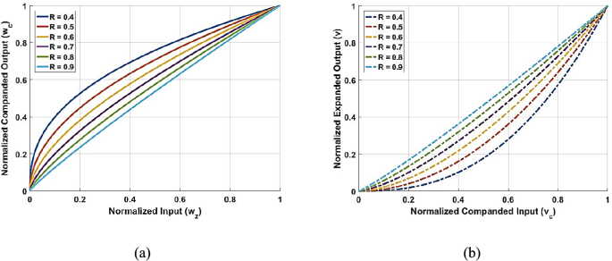
Characteristic response of the root companding methodology: a Compression function and b Expansion function
2.3.1.2 Logarithmic companding technique
The logarithmic companding technique is a nonlinear companding approach aimed at reducing the PAPR in ACO-OFDM systems by compressing the signal’s dynamic range. This technique employs a logarithmic function to reshape the amplitude distribution, effectively reducing signal peaks while maintaining the overall signal structure. The companding function is defined as:
where is the companding factor that determines the level of compression applied to the signal, the impact of the logarithmic function on signal power levels is significant, as it modifies amplitude characteristics in several ways. First, it facilitates peak reduction and dynamic range compression, where high-amplitude signals experience more substantial compression due to the logarithmic function’s gradual increase for larger values. This process limits peak amplitudes and effectively reduces PAPR. At the same time, low-amplitude signals remain mostly unaffected due to for small inputs, preserving essential signal details and preventing unnecessary distortion. Additionally, logarithmic compression helps with power redistribution and noise resilience by redistributing signal power and lowering the average transmitted power, which improves energy efficiency in VLC systems. It also enhances resistance to noise by preventing weaker signals from being excessively attenuated, ensuring signal integrity under channel impairments. At the receiver, an inverse exponential function is applied to reconstruct the original signal, defined as:
This function restores the original dynamic range, ensuring accurate demodulation and maintaining reliable BER performance. Figure 4a presents the normalized companding function of the logarithmic companding technique for different companding factors () ranging from 1 to 10. The curves illustrate how increasing L enhances the compression effect, with higher values leading to stronger signal compression, thereby effectively addressing the high PAPR problem. This demonstrates the nonlinear characteristics of the logarithmic function, where compression intensity increases as L grows. Figure 4b depicts the corresponding normalized expansion function, which reconstructs the original signal during the expansion phase. Due to the exponential nature of the expansion function, the signal grows rapidly as increases. However, for larger values, the division by moderates this growth, causing the expander output values to converge or appear nearly identical for the same values. This behavior highlights the technique’s ability to balance compression and expansion, ensuring accurate signal recovery while effectively reducing the dynamic range during transmission. Overall, logarithmic companding is an effective technique for ACO-OFDM-based VLC systems, where PAPR reduction is essential to mitigating LED nonlinearity. This approach improves power efficiency and integrity by compressing high amplitudes while preserving small signal variations. However, selecting an appropriate companding factor is crucial to balancing PAPR reduction, BER performance, and computational complexity for optimal system performance.
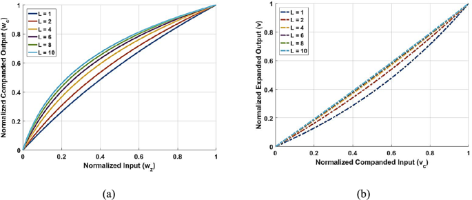
Characteristic response of the logarithmic companding technique: a Compression function and b Expansion function
2.3.1.3 Hyperbolic tangent companding technique
The hyperbolic tangent companding technique is designed to mitigate high PAPR in ACO-OFDM systems by compressing the dynamic range of the O-OFDM signal. This method employs a nonlinear companding function based on the tanh function, effectively reducing peak amplitudes while preserving low-amplitude components to prevent excessive distortion. The companding function is given as follows:
where is the companding factor that controls the degree of compression, the impact of the tanh function on signal power levels can be understood in several ways. First, it compresses high-amplitude signals, preventing extreme fluctuations contributing to high PAPR. This is due to the asymptotic nature of the tanh function, which gradually saturates at ± 1, thereby limiting peak values. Second, small-amplitude signals remain nearly unchanged, as for small x, ensuring that low-energy components are preserved and preventing unnecessary attenuation. As a result, the overall power of the signal is redistributed, reducing average power while maintaining essential signal characteristics. This is particularly beneficial for power-efficient transmission in VLC systems, where LED nonlinearity is a key concern.
Despite these advantages, the non-linear compression introduced by the tanh function can introduce signal distortion, mainly if the companding factor is too large. Therefore, selecting an optimal value is crucial to achieving a balance between PAPR reduction and BER performance. At the receiver, an inverse companding function is applied to reconstruct the original signal:
This operation helps restore the compressed signal while compensating for non-linear transformations introduced during transmission. Figure 5a illustrates the compander function of the hyperbolic tangent companding technique, applied to normalized input values ranging from 0 to 1, representing the signal prepared for transmission. The companding factor () controls the degree of compression, with larger values of resulting in more substantial compression, especially near the upper end of the input range. The tanh function is inherently nonlinear, saturating at higher input values while amplifying smaller inputs more than larger ones. When T is small (e.g., T = 1), the function remains nearly linear, as behaves linearly around the origin. In contrast, for larger T values (e.g., T = 11), the compression effect intensifies, causing the curve to flatten more quickly, highlighting the nonlinear characteristics of tanh.
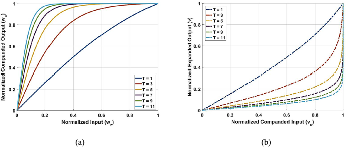
Characteristic response of the hyperbolic tangent companding technique: a Compression function and b Expansion function
Figure 5b depicts the expander function, which reconstructs the original input signal from the normalized companded output. This process is achieved using the inverse hyperbolic tangent function () to reverse the nonlinear compression introduced by . Similar to the compander, the expander’s behavior is influenced by T. A larger T demands greater precision during expansion to counteract the more substantial compression. When T is small, the expanded output closely resembles the companded input due to the mild compression effect. However, the expanded curves deviate more significantly for larger T values, reflecting the pronounced nonlinear impact of both tanh and its inverse function. In summary, the hyperbolic tangent companding technique effectively reduces PAPR by limiting peak amplitudes, redistributing power levels, and preserving more minor signal variations. When properly optimized, this technique offers an efficient approach for VLC systems, balancing PAPR reduction and signal integrity.
2.3.1.4 A-law companding technique
The A-Law companding technique is a logarithmic compression method used to compress the dynamic range of an input signal. This technique reduces the signal’s high amplitude peaks while compressing the lower amplitude values, improving transmission efficiency and minimizing distortion. The A-Law companding function maps the input signal amplitudes to corresponding output values using a logarithmic formula designed for use in communication systems with large signal ranges. It is expressed as (Khalaf et al. 2023; Mohammed et al. 2021):
where is the time-domain sampled signal that modulates the LED intensity, is the output companded signal, is the companding factor, ranging from 1 to 87.6, and is the maximum value of the time-domain signal. This function compresses smaller amplitude signals and provides a smooth transition for more significant amplitude signals, thereby reducing the dynamic range. For values of below , the logarithmic transformation is applied to compress the signal. The compression becomes more gradual for larger values, ensuring that high-amplitude signals are not over-compressed. An inverse expansion function is used at the receiver to recover the original signal. The expansion is given by:
where is the received companded signal, is the expanded signal after the inverse operation, and is the maximum value of the received companded signal. The inverse expansion function restores the signal by reversing the companding process, expanding the compressed signal back to its original amplitude range, thus recovering the transmitted signal. The expansion maintains the signal’s integrity while compensating for the compression applied during the transmission. The A-Law technique has several advantages, such as effective dynamic range compression and improved signal fidelity due to its smooth logarithmic function. However, it is less effective than other companding methods, such as root companding, concerning PAPR reduction. Additionally, improper selection of the companding factor can lead to BER degradation, particularly in low energy per bit to noise power spectral density ratio environments, as it may cause signal distortion. The effectiveness of A-Law depends on the careful tuning of the companding factor, and incorrect calibration can impact performance under varying operating conditions. In conclusion, A-Law is an efficient method for compressing signal dynamic ranges, balancing transmission efficiency and signal integrity. However, carefully selecting the companding factor is essential to achieve optimal performance.
Figure 6a illustrates the companding function characteristics of the A-Law companding technique for different companding factors ( = 1, 3, 5, 7, and 9). The graph demonstrates that the compression effect becomes more pronounced as the companding factor increases, especially for higher input values. A more significant value causes the curve to deviate further from the linear reference ( = 1), emphasizing the nonlinear nature of A-Law companding. This technique effectively reduces the PAPR while preserving the integrity of lower-amplitude signal components.
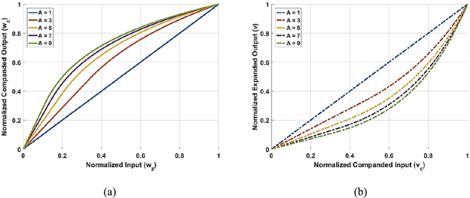
Characteristic response of the A-law companding technique: a Compression function and b Expansion function
Figure 6b presents the expansion function characteristics corresponding to the A-Law companding technique. It illustrates how the original signal is reconstructed from the companded input for different companding factors. When is small (e.g., = 1), the expansion curve remains nearly linear, indicating minimal alteration to the signal. However, as A increases, the expansion effect becomes more significant, particularly for higher input values, demonstrating the nonlinear behavior of the inverse companding process. Larger values lead to greater deviations from the linear reference, reflecting the stronger compression applied in the companding stage. This characteristic ensures that signals with higher compression are accurately expanded, preserving signal integrity while effectively mitigating PAPR effects.
2.3.1.5 µ-law companding technique
The µ-Law companding technique is a nonlinear companding method used to compress the dynamic range of input signals, similar to the A-Law technique but with a different compression function (Hameed et al. 2021; Mohammed et al. 2021; Ramazan et al. 2023). The µ-Law method compresses higher amplitudes more than lower ones, effectively minimizing the signal’s dynamic range. This is particularly beneficial in communication systems, where reducing the dynamic range of signals enhances transmission efficiency and reduces distortion. The µ-Law companding function uses a logarithmic formula to map the input signal’s amplitude to a corresponding output value. The function can be expressed as:
Here, represents the time-domain sampled, is the output companded sampled, μ is the companding factor (typically ranging from 1 to 255), and is the maximum value of the time-domain signal. This function effectively compresses higher amplitudes while maintaining lower amplitudes, resulting in a more compact signal with a reduced dynamic range. At the receiver, the inverse of the companding function is applied to recover the original signal, expressed as:
where is the received companded signal, is the expanded signal after the inverse operation, and is the maximum value of the received companded signal. The inverse function restores the original signal by expanding it back to its initial amplitude range, with the sign function preserving the phase of the signal. One of the key advantages of the µ-Law technique is its ability to efficiently compress the dynamic range, particularly for high-amplitude signals, which helps mitigate PAPR issues. Additionally, its logarithmic function ensures a smooth transition between lower and higher amplitude values, preserving signal integrity. However, while effectively reducing the dynamic range, the µ-Law technique is less efficient at lowering the PAPR than other methods like root companding. Furthermore, the performance of µ-Law heavily depends on the proper selection of the companding factor μ; an incorrect choice can lead to signal distortion or BER degradation, particularly in low conditions. In conclusion, while the µ-Law companding technique offers efficient compression and optimal performance, it relies on careful tuning of the companding factor μ. The technique balances signal recovery quality and PAPR mitigation.
The compression and expansion characteristics of the signal are directly influenced by the μ parameter, as observed in Fig. 7. Higher amplitude signals are mapped to a smaller range in the compression function, as demonstrated in Fig. 7a, while lower amplitude signals experience minimal distortion. As μ increases, the compression effect becomes more pronounced, particularly for higher input values, leading to significant PAPR reduction. For small μ values (e.g., μ = 1 or 3), the compression is relatively mild, preserving much of the original signal shape with minimal distortion. Conversely, when μ is large (e.g., μ = 9), the compression effect becomes stronger, flattening high-amplitude regions and reducing signal peaks more aggressively. However, this increased compression also complicates accurate signal recovery.